What this calculator does
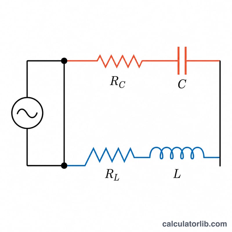
This tool computes the total complex impedance of an AC network where a series-RC branch (a resistor R_C in series with a capacitor C) is connected in parallel with a series-RL branch (a resistor R_L in series with an inductor L), all driven at a sinusoidal frequency f. It reports the impedance magnitude \(|Z|\) in kOhm, Ohm and mOhm, plus the phase angle in degrees and radians.
How to use it
Enter each component value and pick its unit from the dropdown (the factor converts to SI). Provide the drive frequency and its unit, then read the magnitude and phase. A positive phase angle means the network is net inductive (current lags the voltage); a negative angle means it is net capacitive (current leads).
The formula explained
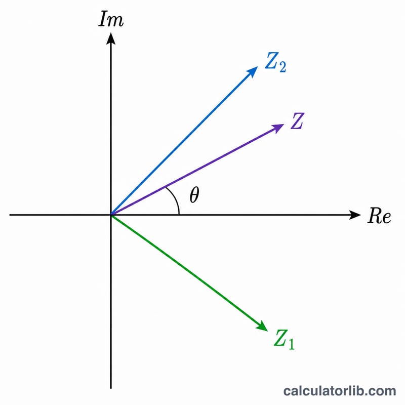
The capacitor contributes a reactance \(X_c = \frac{1}{\omega\cdot C}\) and the inductor \(X_l = \omega\cdot L\), where \(\omega = 2\pi f\). The branches are written as complex numbers \(Z_1 = R_C - jX_c\) and \(Z_2 = R_L + jX_l\). They combine using the parallel rule $$Z = \left|\frac{Z_1 \cdot Z_2}{Z_1 + Z_2}\right|$$ Multiplying numerator and denominator by the conjugate of the denominator gives the real and imaginary parts \(Z_r\) and \(Z_i\), from which \(|Z| = \sqrt{Z_r^2 + Z_i^2}\) and \(\text{phase} = \operatorname{atan2}(Z_i, Z_r)\).
Worked example
With R_C = 10 Ohm, C = 500 uF, R_L = 10 Ohm, L = 2 mH and f = 1 kHz: \(\omega = 6283.19\ \text{rad/s}\), \(X_c = 0.3183\ \text{Ohm}\) and \(X_l = 12.566\ \text{Ohm}\). Working the complex algebra gives \(Z_r = 6.5092\) and \(Z_i = 2.1378\), so $$|Z| = 6.851\ \text{Ohm} \qquad \text{phase} = +18.15^\circ$$ i.e. slightly inductive.
FAQ
What does a positive phase mean? The overall network behaves inductively, so the current lags the applied voltage.
What happens at DC (f = 0)? The capacitor blocks DC, so the RC branch is open and only the RL branch conducts. This tool treats very low or zero frequency as the open-capacitor limit.
Why three impedance units? kOhm, Ohm and mOhm are the same value at different scales so you can read whichever matches your circuit conveniently.