What This Calculator Does
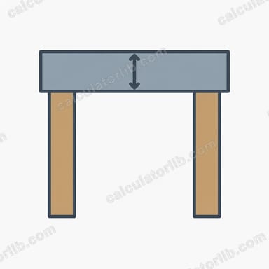
The Door Header Size Calculator estimates the minimum depth of a header (lintel) beam spanning a door opening. It works from four engineering inputs — the clear span, the total uniform load carried, the allowable bending stress of your material, and the chosen header width — and returns the maximum bending moment, the required section modulus, and the minimum beam depth needed to resist bending.
How to Use It
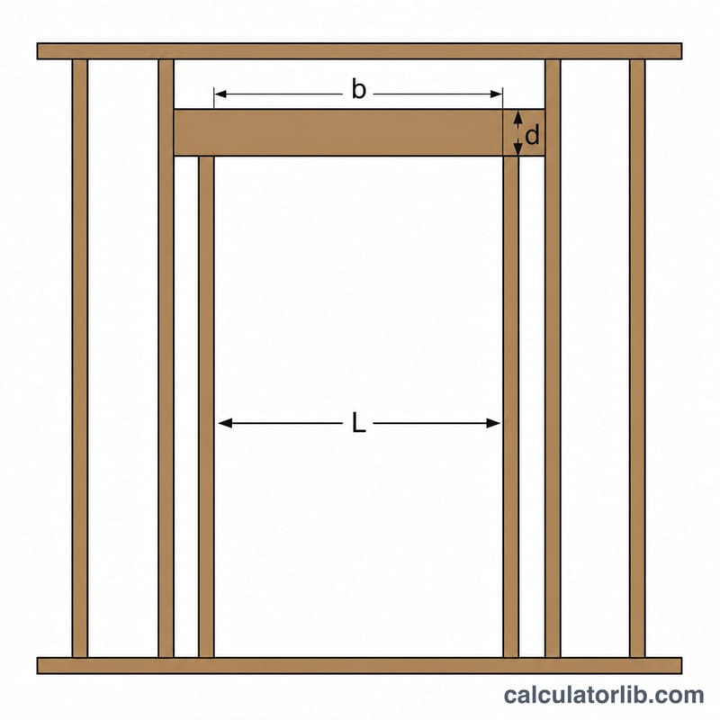
Enter the door opening width as the span in feet. Enter the total uniform load on the header in pounds per linear foot (combine dead and live tributary loads). Enter the allowable bending stress (Fb) in psi for your lumber or material — for example, common framing lumber ranges from roughly 850–1500 psi after adjustment factors. Enter the header width (b) in inches, such as 3 in for a doubled 2x. The calculator outputs the required depth in inches; round up to a standard lumber size.
The Formula Explained
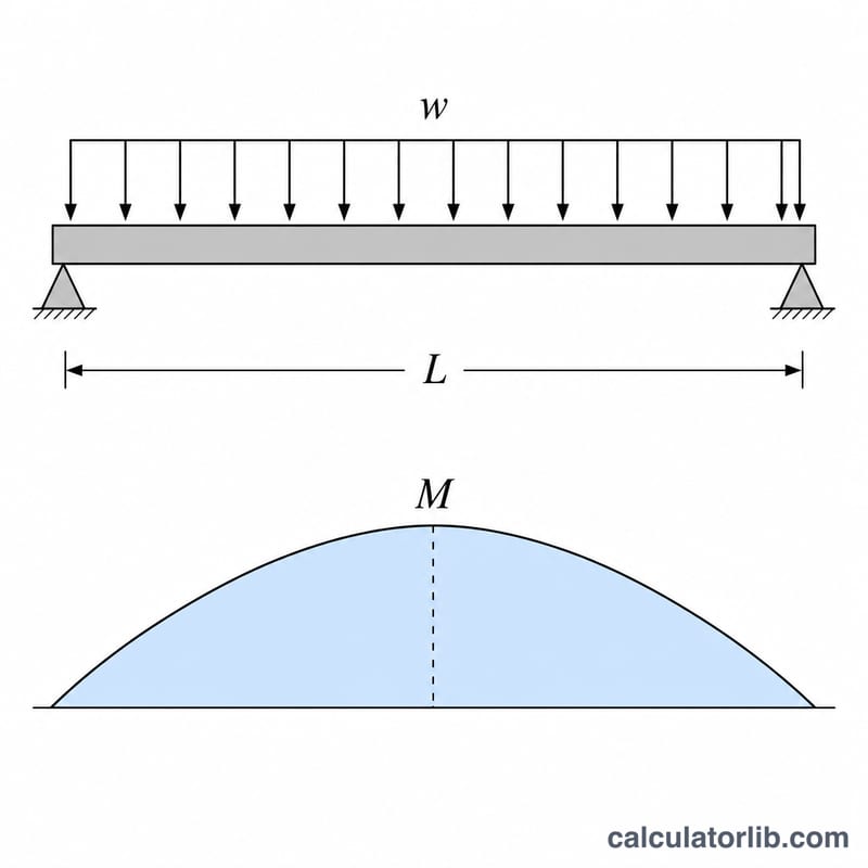
For a simply supported beam carrying a uniform load, the maximum bending moment is \(M = \dfrac{wL^{2}}{8}\). Bending stress relates to moment through the section modulus \(S\), where \(S = \dfrac{M}{F_b}\). For a solid rectangular cross-section, \(S = \dfrac{b \cdot d^{2}}{6}\). Solving for depth gives $$d = \sqrt{\dfrac{6S}{b}}.$$ The moment is converted from lb\(\cdot\)ft to lb\(\cdot\)in (\(\times 12\)) so that all stress units stay consistent in psi.
Worked Example
Span \(L = 6\) ft, load \(w = 400\) lb/ft, \(F_b = 1000\) psi, width \(b = 3\) in. Moment $$M = \frac{400 \times 6^{2}}{8} = 1800 \text{ lb}\cdot\text{ft} = 21{,}600 \text{ lb}\cdot\text{in}.$$ Section modulus $$S = \frac{21{,}600}{1000} = 21.6 \text{ in}^{3}.$$ Depth $$d = \sqrt{\frac{6 \times 21.6}{3}} = \sqrt{43.2} \approx 6.57 \text{ in},$$ so a member at least ~6.6 in deep (e.g. a 2x8 pair) is needed.
FAQ
Is this a code-approved design? No. This is a quick sizing estimate using allowable stress design. Always verify against your local building code and an engineer, including deflection and shear checks.
What about deflection? This tool checks bending only. Long spans are often governed by deflection limits (L/240 or L/360), so confirm separately.
What width should I enter? Use the combined thickness of the plies — two 1.5 in members give \(b = 3\) in; three give 4.5 in.