What Is Heat Exchanger Sizing?
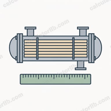
Heat exchanger sizing determines how much heat transfer surface area a device needs to move a target amount of thermal energy between a hot and a cold stream. The larger the required duty or the smaller the temperature driving force, the more area you need. This calculator uses the classic Log Mean Temperature Difference (LMTD) method, the standard first-pass approach for shell-and-tube and plate exchangers.
How to Use This Calculator
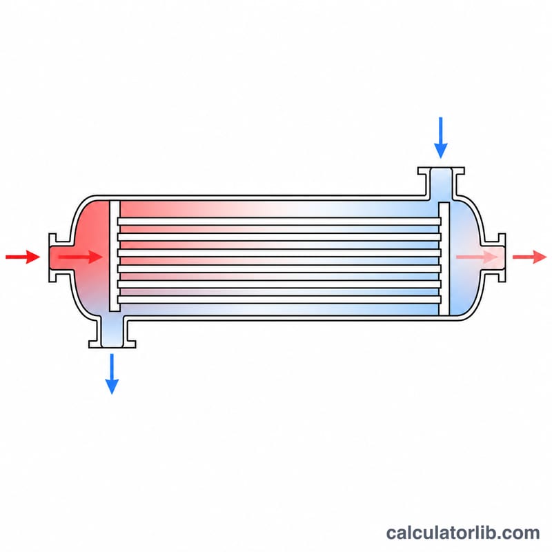
Choose the flow arrangement (counterflow or parallel flow), then enter the hot fluid mass flow rate, its specific heat, and the four stream temperatures: hot inlet, hot outlet, cold inlet, and cold outlet. Finally, supply the overall heat transfer coefficient \(U\). The tool returns the heat duty, the LMTD, and the required surface area.
The Formula Explained
The heat duty comes from the hot-side energy balance, \(Q = \dot{m}\, c_p\,(T_{h,in}-T_{h,out})\), where \(\dot{m}\) is mass flow (kg/s) and \(c_p\) is specific heat (J/kg·K). The driving force is the log mean temperature difference, and the required area follows as:
$$ A = \frac{Q}{U \times \Delta T_{lm}} $$
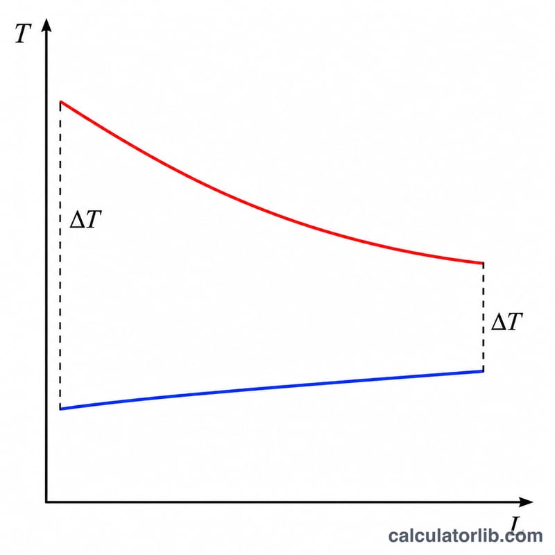
Here \(A\) = surface area in m², \(U\) = overall heat transfer coefficient in W/m²·K, and \(\Delta T_{lm}\) = LMTD in °C. For counterflow, \(\Delta T_1 = T_{h,in}-T_{c,out}\) and \(\Delta T_2 = T_{h,out}-T_{c,in}\).
Worked Example
Water flows at 2 kg/s with \(c_p = 4186\) J/kg·K, cooling from 80°C to 50°C while heating a cold stream from 20°C to 40°C, with \(U = 500\) W/m²·K in counterflow.
$$ Q = 2 \times 4186 \times (80-50) = 251160\,\text{W} $$
$$ \Delta T_{lm} = \frac{40 - 30}{\ln(40/30)} = 34.76\,\text{°C} $$
$$ A = \frac{251160}{500 \times 34.76} = 14.45\,\text{m}^2 $$
Typical U and Specific Heat Values
The two hardest inputs to estimate for this calculator are the overall heat transfer coefficient \(U\) and the fluid specific heat \(c_p\). The tables below give commonly cited design ranges from standard heat-transfer references (for example Perry's Chemical Engineers' Handbook and typical shell-and-tube design guides). These are approximate, order-of-magnitude figures for preliminary sizing only — actual values depend on fluid velocity, fouling, pressure, temperature and exchanger geometry, so a detailed rating should be done before final design.
Overall heat transfer coefficient \(U\)
| Service (hot–cold pair) | Typical \(U\) (W/m²·K) |
|---|---|
| Steam (condensing) – water | 1000 – 3500 |
| Water – water | 800 – 1500 |
| Steam (condensing) – light organic liquid | 500 – 1000 |
| Water – light oil | 100 – 350 |
| Water – heavy oil / viscous liquid | 50 – 300 |
| Gas (near atmospheric) – gas | 10 – 50 |
Higher values in each range correspond to clean surfaces, turbulent flow and phase change; lower values reflect fouling, laminar flow or high-viscosity fluids. For the calculator, use \(U\) in W/m²·K so the computed area comes out in m² with \(Q\) in watts.
Specific heat \(c_p\) of common fluids
| Fluid | Approx. \(c_p\) (J/kg·K) | Conditions |
|---|---|---|
| Liquid water | 4186 | near 20–25 °C |
| Ethylene glycol (pure) | ~2400 | near room temperature |
| Light hydrocarbon / mineral oil | ~1900 | varies strongly with grade and temperature |
| Air (dry) | ~1005 | near room temperature, constant pressure |
Specific heat rises modestly with temperature for most liquids and gases, and glycol–water mixtures fall between the pure-glycol and pure-water values in proportion to concentration. When you enter \(c_p\), match the units of your mass flow rate: with \(c_p\) in J/kg·K and \(\dot m\) in kg/s, the heat duty \(Q = \dot m \, c_p \, \Delta T\) comes out in watts, which pairs directly with a \(U\) in W/m²·K in the area equation \(A = \dfrac{Q}{U \times \Delta T_{lm}}\).
FAQ
Counterflow vs parallel flow? Counterflow yields a larger LMTD for the same terminal temperatures, so it needs less area — it is almost always preferred.
Where do I get U? \(U\) is estimated from film coefficients, wall conductivity, and fouling factors, or taken from published tables for the fluid pair.
Is this a final design? No. LMTD sizing is a first estimate; multi-pass exchangers need an \(F\) correction factor, and mechanical design refines the geometry.