What this calculator does
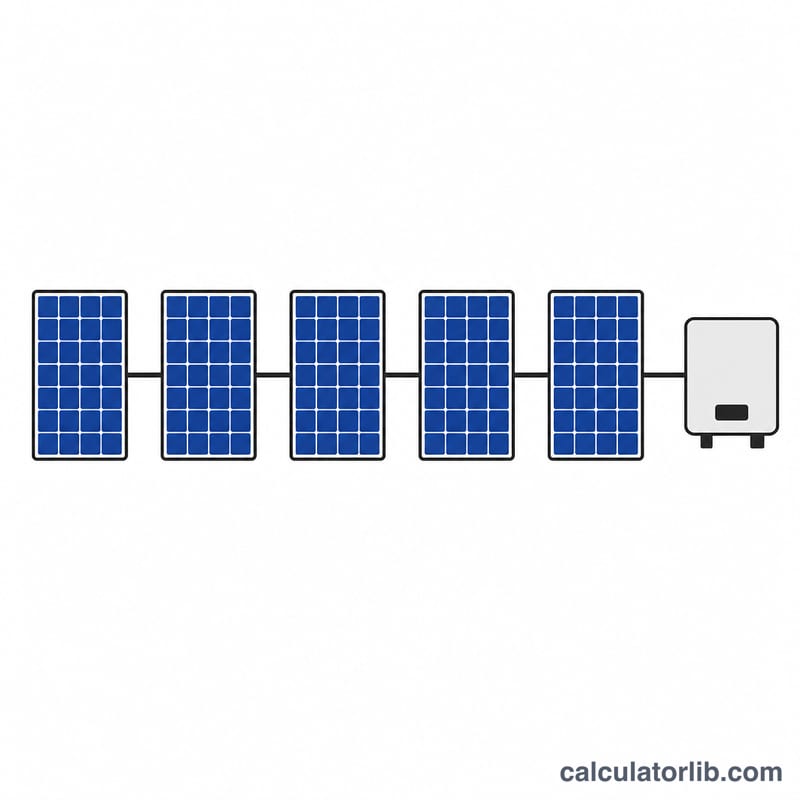
String sizing is the step in solar design where you decide how many photovoltaic (PV) modules to wire in series to form a string. Wire too many and the array voltage on a freezing morning can exceed the inverter maximum input rating and damage it; wire too few and the string voltage on a hot afternoon can drop below the inverter minimum MPPT threshold, so the inverter stops tracking and you lose energy. This tool finds the safe count at both extremes.
The formula explained
Open-circuit voltage grows as cells get colder. With \(V_{oc,STC}\) = module open-circuit voltage at standard test conditions, \(\beta\) = temperature coefficient of Voc in %/°C (a negative number), and \(T_{min}\) = coldest expected cell temperature:
$$V_{oc}(T_{min}) = V_{oc,STC}\left(1 + \frac{\beta}{100}(T_{min} - 25)\right)$$
The maximum modules per string keeps the cold-weather string voltage under the inverter limit \(V_{max}\):
$$N_{max} = \left\lfloor \frac{V_{max}}{V_{oc}(T_{min})} \right\rfloor$$
The minimum uses the hot-temperature max-power voltage \(V_{mp}(T_{max})\) against the inverter minimum MPPT voltage \(V_{mppt,min}\): \(N_{min} = \lceil V_{mppt,min} / V_{mp}(T_{max}) \rceil\).
How to use it
Enter the module Voc and Vmp from the datasheet, the Voc temperature coefficient, your inverter maximum DC input and minimum MPPT voltage, and the coldest and hottest cell temperatures at your site. The result shows the allowable range of modules per string.
Worked example
With \(V_{oc,STC}=40\) V, \(\beta=-0.30\) %/°C, \(V_{max}=600\) V and \(T_{min}=-10\) °C:
$$V_{oc}(-10) = 40\left(1 + \frac{-0.30}{100}(-10 - 25)\right) = 44.2\ \text{V}$$
$$N_{max} = \left\lfloor \frac{600}{44.2} \right\rfloor = 13$$
With \(V_{mp}=32\) V, \(T_{max}=70\) °C and \(V_{mppt,min}=200\) V: \(V_{mp}(70)=27.68\) V so $$N_{min} = \left\lceil \frac{200}{27.68} \right\rceil = 8.$$ A string of 8 to 13 modules is safe.
Definitions & Glossary
String sizing is the process of choosing how many modules to wire in series so the string's voltage stays inside the inverter's allowed window at every temperature the site will ever see. The terms below define the quantities used in that calculation.
- Voc (open-circuit voltage) — the voltage a PV module produces with no load connected (terminals open). It is the highest voltage a single module reaches and is the value that drives the upper string limit.
- Vmp (maximum-power voltage) — the voltage at the module's maximum-power point (the operating voltage under load). It is lower than Voc and drives the lower string limit, because the string must still exceed the inverter's MPPT minimum when hot.
- STC (Standard Test Conditions) — the reference conditions at which datasheet Voc and Vmp are measured: 1000 W/m² irradiance, air mass AM1.5, and a cell temperature of 25°C. STC is defined in the international standards IEC 60904 / IEC 61215.
- Temperature coefficient of Voc (β, %/°C) — how much Voc changes per degree of cell temperature away from 25°C. For crystalline-silicon modules β is negative (typically about −0.27 to −0.35 %/°C), so Voc rises as temperature drops below 25°C. This is why the coldest expected temperature produces the worst-case high voltage.
- MPPT (Maximum Power Point Tracking) — the inverter circuit that continuously adjusts its operating voltage to keep the array at its maximum-power point.
- MPPT minimum voltage (vmppt_min) — the lowest string voltage at which the inverter can still track and produce full power. When modules are hot, Vmp falls; the string must stay above this floor, setting the minimum module count.
- Inverter maximum DC input voltage (vmax) — the absolute voltage ceiling the inverter's DC input can tolerate. Exceeding it can damage the inverter and is a safety/warranty violation, so the cold-weather string voltage must stay below it. Common classes are 600 V, 1000 V, and 1500 V.
- String vs array — a string is a set of modules wired in series (their voltages add); an array is one or more strings, often wired in parallel (their currents add). String sizing concerns the series count within one string.
- Series wiring — connecting module positive to next module negative so voltages sum. \(N\) identical modules in series give a string voltage of \(N \times V_{module}\).
- Cold / hot cell temperature — the extreme cell temperatures used for design. The cold extreme (site record low ambient) maximizes Voc and sets \(N_{max}\); the hot extreme (cell temperature well above ambient in full sun, often 60–75°C) minimizes Vmp and sets \(N_{min}\).
Standards note: the exact temperature you must design to is set by local code, not by this tool. In the United States, NEC (NFPA 70) Article 690.7 requires the maximum voltage to be evaluated at the site's lowest expected ambient temperature (often taken from ASHRAE extreme-low data). Other countries use their own conventions, so confirm the required design temperatures for your jurisdiction.
String Sizing Across Different Scenarios
The maximum module count comes from the cold-temperature Voc, and the minimum from the hot-temperature Vmp:
$$N_{max} = \left\lfloor \frac{ V_{max}}{V_{oc}\left(1 + \frac{\beta}{100}(T_{min}-25)\right)} \right\rfloor \qquad N_{min} = \left\lceil \frac{ V_{mppt,min}}{V_{mp}\left(1 + \frac{\beta}{100}(T_{max}-25)\right)} \right\rceil$$
The table below applies these to several realistic setups. To keep the comparison to the single temperature coefficient this tool uses, \(N_{min}\) applies the same \(\beta\) to Vmp; note that real datasheets list a separate, usually more negative, coefficient for Vmp, so treat the minimums as approximate. Values assume Tmax = 70°C cell temperature except the mild-climate row.
| Scenario | Module Voc / Vmp / β | Inverter Vmax / Vmppt_min | Tmin / Tmax | Voc(cold) | Nmin | Nmax | Safe range |
|---|---|---|---|---|---|---|---|
| Cold climate, 1000 V | 40 V / 33 V / −0.30 %/°C | 1000 V / 250 V | −25°C / 70°C | 46.0 V | 9 | 21 | 9–21 |
| Mild climate, 1000 V | 40 V / 33 V / −0.30 %/°C | 1000 V / 250 V | 0°C / 65°C | 43.0 V | 9 | 23 | 9–23 |
| Cold climate, 600 V | 40 V / 33 V / −0.30 %/°C | 600 V / 150 V | −25°C / 70°C | 46.0 V | 6 | 13 | 6–13 |
| Cold climate, 1500 V | 40 V / 33 V / −0.30 %/°C | 1500 V / 400 V | −25°C / 70°C | 46.0 V | 15 | 32 | 15–32 |
| Cold climate, higher Voc / worse β | 50 V / 41 V / −0.35 %/°C | 1000 V / 250 V | −25°C / 70°C | 58.75 V | 8 | 17 | 8–17 |
Worked substitution (row 1). Cold Voc: \(V_{oc,cold} = 40\left(1 + \frac{ -0.30}{100}(-25-25)\right) = 40(1.15) = 46.0\text{ V}\), so \(N_{max} = \left\lfloor \frac{ 1000}{46.0} \right\rfloor = 21\). Hot Vmp: \(V_{mp,hot} = 33\left(1 + \frac{ -0.30}{100}(70-25)\right) = 33(0.865) = 28.5\text{ V}\), so \(N_{min} = \left\lceil \frac{ 250}{28.5} \right\rceil = 9\).
How to read the comparison:
- Colder climates narrow the top of the range. Dropping Tmin from 0°C to −25°C lifts cold Voc from 43.0 V to 46.0 V, cutting the same 1000 V inverter from 23 to 21 modules.
- Higher-voltage inverters widen the range. With the identical module and cold extreme, the ceiling grows from 13 (600 V) to 21 (1000 V) to 32 (1500 V) modules.
- Higher Voc and a more negative β shrink the range. The 50 V / −0.35 %/°C module reaches 58.75 V cold, so only 17 modules fit on the 1000 V inverter versus 21 for the 40 V / −0.30 %/°C module.
These figures are illustrative engineering examples, not product specifications. Always size against your specific module datasheet, your inverter's published limits, and the design temperatures required by your local electrical code.
FAQ
Why use the coldest temperature for the maximum? Voc peaks in cold weather, so the highest string voltage the inverter ever sees happens then.
What temperature coefficient should I enter? Use the module datasheet Voc coefficient, typically around -0.28 to -0.35 %/°C.
Does it account for the MPPT range? Yes, the minimum count keeps the hot-weather voltage above the inverter lower MPPT limit.