What is a Thin-Film Optical Coating Calculator?
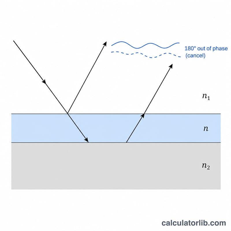
Anti-reflection (AR) coatings reduce unwanted reflections from lenses, displays, and optical windows. The most common design is the quarter-wave coating: a single thin layer whose optical thickness equals one quarter of the design wavelength. At that thickness, light reflected from the top of the film and light reflected from the substrate interface arrive a half-wavelength out of phase and destructively interfere, cancelling the reflection. This calculator returns the required physical layer thickness from your design wavelength and the coating material's refractive index.
How to use it
Enter the design wavelength \(\lambda\) in nanometers (e.g. 550 nm for the green center of the visible spectrum), the refractive index \(n\) of the coating material (e.g. 1.38 for magnesium fluoride, MgF₂), and the order \(m\). Use \(m = 1\) for the thinnest single quarter-wave layer; higher odd orders (3, 5, …) give thicker layers that work at the same wavelength but over a narrower band. The result gives both physical thickness and optical thickness.
The formula explained
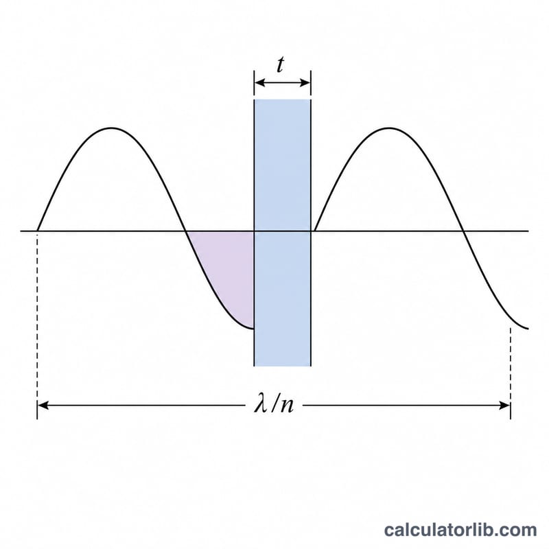
The physical thickness is $$t = \frac{m\lambda}{4n}.$$ The factor \(1/n\) converts the optical path \((m\lambda/4)\) into a real geometric thickness inside the higher-index film, since light travels slower and has a shorter effective wavelength \(\lambda/n\) inside the material. The optical thickness \(n\cdot t\) therefore equals \(m\lambda/4\), an odd multiple of a quarter wave — the condition for an AR minimum.
Worked example
For \(\lambda = 550\) nm, \(n = 1.38\) (MgF₂), and \(m = 1\): $$t = \frac{1 \times 550}{4 \times 1.38} = \frac{550}{5.52} \approx 99.64 \text{ nm}.$$ So a single MgF₂ layer about 100 nm thick minimizes reflection at green light. Its optical thickness is \(1.38 \times 99.64 \approx 137.5\) nm \(= 550/4\).
Common AR Coating Materials and Refractive Indices
The table lists approximate refractive indices near 550 nm for materials often used in thin-film optical coatings. Use these as starting values for the index field \(n\) in the calculator.
| Material | Approx. index n (near 550 nm) | Typical role |
|---|---|---|
| MgF₂ (magnesium fluoride) | ~1.38 | Low index |
| SiO₂ (silicon dioxide) | ~1.46 | Low index |
| Al₂O₃ (aluminum oxide) | ~1.76 | Medium index |
| Si₃N₄ (silicon nitride) | ~2.0 | Medium/high index (common on silicon solar cells) |
| Ta₂O₅ (tantalum pentoxide) | ~2.1 | High index |
| ZnS (zinc sulfide) | ~2.3 | High index |
| TiO₂ (titanium dioxide) | ~2.3–2.4 | High index |
Note: These values are approximate. The real index depends on the deposition method (evaporation, sputtering, ion-assisted, ALD), film density, crystal structure and wavelength. Use measured or supplier data for precise designs.
Thickness Comparison Across Wavelengths and Materials
Each value is computed with \(t = \dfrac{m\lambda}{4n}\), using MgF₂ (\(n=1.38\)) and SiO₂ (\(n=1.46\)). Thicknesses are in nm and rounded to two decimals. Rows are order \(m=1\) unless noted.
| Design wavelength λ | Order m | MgF₂ (n = 1.38) | SiO₂ (n = 1.46) |
|---|---|---|---|
| 450 nm | 1 | 81.52 nm | 77.05 nm |
| 550 nm | 1 | 99.64 nm | 94.18 nm |
| 633 nm | 1 | 114.67 nm | 108.39 nm |
| 1064 nm | 1 | 192.75 nm | 182.19 nm |
| 1550 nm | 1 | 280.80 nm | 265.41 nm |
| 550 nm | 3 | 298.91 nm | 282.53 nm |
Example substitution for the first highlighted row: \(t = \dfrac{1 \cdot 550}{4 \cdot 1.38} = \dfrac{550}{5.52} \approx 99.64\) nm. For \(m=3\): \(t = \dfrac{3 \cdot 550}{5.52} = \dfrac{1650}{5.52} \approx 298.91\) nm.
Interpreting the Thickness Result
The result is the ideal single-layer thickness for the chosen design wavelength only. At that wavelength the optical path in the film, \(n t\), equals a quarter wave (for \(m=1\)). Light reflected from the top and bottom film surfaces then interferes destructively, so reflection is at a minimum. Higher orders (\(m=3, 5,\dots\)) give the same null at \(\lambda\) but are thicker and have a narrower usable band.
- Residual reflection: The null is not perfect with common materials. For MgF₂ (\(n\approx1.38\)) on crown glass (\(n_s\approx1.52\)), reflectance at the design wavelength is \(R=\left(\dfrac{n_s-n_f^2}{n_s+n_f^2}\right)^2 \approx 1.3\%\) per surface, compared with about 4% for uncoated glass.
- Ideal index: Zero reflection at normal incidence needs \(n_f=\sqrt{n_s}\). For glass this is about 1.23, lower than any common durable film, so a single layer cannot reach zero.
- Bandwidth: The minimum is broadband-limited. Reflectance rises on both sides of \(\lambda\).
- Angle of incidence: The null shifts toward shorter wavelengths as the angle increases, because the optical path through the film changes.
- Broader bands: Multilayer AR stacks, or V-coat designs optimized for one wavelength, give much lower reflectance. Broadband multilayers give low reflectance over a wide range.
Assumptions: The formula assumes normal incidence and a non-dispersive (constant) refractive index. In real films the index varies with wavelength, so check the final design with a full thin-film simulation or supplier data.
FAQ
Why must the order be odd? Only odd multiples of a quarter wave produce the half-wavelength round-trip phase needed for destructive interference; even multiples behave like an absentee layer.
What refractive index is ideal for a single-layer AR coating? The reflection vanishes completely when \(n_{\text{film}} = \sqrt{n_{\text{substrate}}}\). For glass (\(n \approx 1.5\)), that ideal is about 1.22; MgF₂ at 1.38 is the practical low-index choice.
Can I use this for high-reflector mirror stacks? The same quarter-wave thickness rule applies to each layer in a multilayer dielectric stack, though full stack performance requires transfer-matrix analysis.