What is the CNC lathe feed rate calculator?
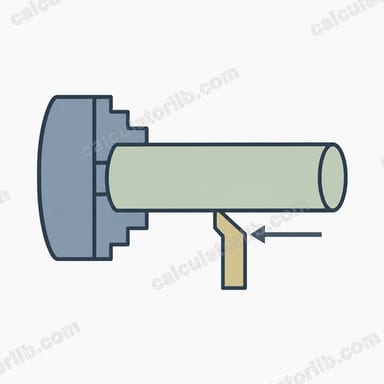
This calculator converts the basic turning parameters of a CNC lathe into the numbers a machinist actually programs: the linear feed rate in mm/min and the surface cutting speed in m/min. It also gives imperial equivalents (in/min and SFM) and an estimated cutting time for a pass of a given length. The formulas are universal geometry and kinematics, so they apply to any lathe.
How to use it
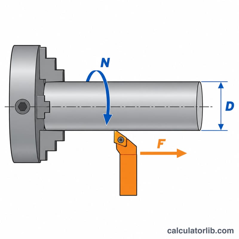
Enter the workpiece diameter in millimetres, the spindle speed in RPM and the feed per revolution in mm/rev. Optionally enter the length of the cut to estimate machining time. The calculator returns the feed rate, cutting speed and time instantly. If your control runs in G99 (feed per revolution) you program f directly; in G98 (feed per minute) you program the calculated feed rate.
The formulas explained
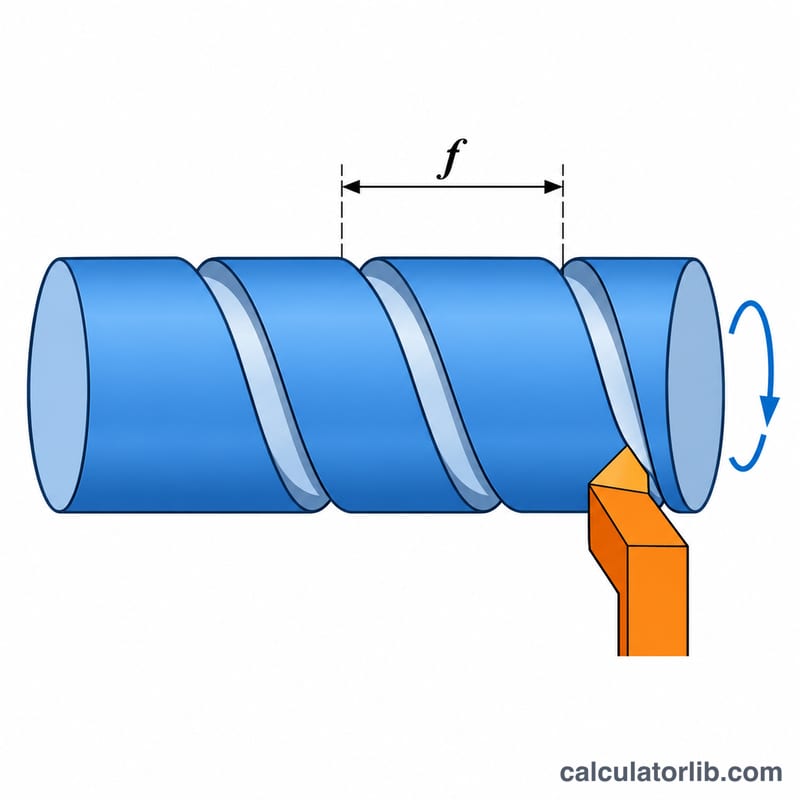
Feed rate is the distance the tool travels per minute:
$$F = N \times f$$where \(N\) = spindle speed in RPM and \(f\) = feed per revolution in mm/rev. Cutting speed is the speed of the surface passing the tool edge:
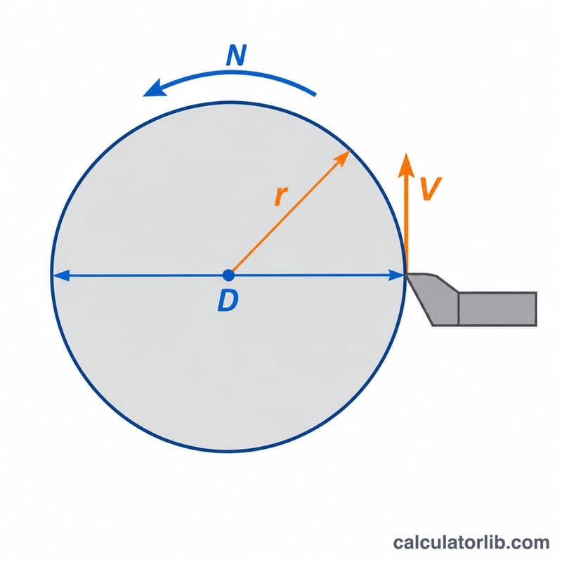
$$V_c = \frac{\pi \times D \times N}{1000}$$where \(D\) = diameter in mm, giving \(V_c\) in m/min. Cutting time for a pass is \(t = L / F\), with \(L\) the cut length in mm.
Worked example
Turning a 50 mm bar at 1200 RPM with a feed of 0.2 mm/rev over a 100 mm length:
$$F = 1200 \times 0.2 = 240\,\text{mm/min}$$$$V_c = \frac{\pi \times 50 \times 1200}{1000} \approx 188.5\,\text{m/min}$$$$t = \frac{100}{240} \approx 0.417\,\text{min}$$In imperial units that is about 9.45 in/min and 618 SFM.
Typical Cutting Speeds by Workpiece Material
Cutting speed \(V_c\) is the surface speed at the tool tip. It links diameter and spindle speed: $$V_c = \frac{\pi \cdot D \cdot N}{1000}$$ with \(D\) in mm, \(N\) in RPM and \(V_c\) in m/min. To convert to surface feet per minute, use SFM ≈ m/min × 3.281. The table gives approximate starting ranges for coated carbide inserts in general-purpose turning.
| Material | Vc, carbide (m/min) | Vc, carbide (SFM) |
|---|---|---|
| Free-cutting steel (e.g. 11SMn30, 12L14) | 200–350 | 650–1150 |
| Mild / medium carbon steel (approx. C15–C45) | 150–250 | 490–820 |
| Stainless steel 304 (austenitic) | 100–180 | 330–590 |
| Grey cast iron | 120–250 | 390–820 |
| Aluminium alloys | 300–800 | 980–2620 |
| Brass (free-cutting) | 200–400 | 660–1310 |
| Titanium (e.g. Ti-6Al-4V) | 40–80 | 130–260 |
Note: these are approximate, general starting values. Always follow the insert or tool manufacturer's catalogue data for the specific grade, geometry, coolant and material condition, because that data takes priority over any generic table. Use lower speeds for interrupted cuts, long overhangs or hard material conditions.
Typical Feed per Revolution Ranges
Feed per revolution \(f_r\) (mm/rev) is the distance the tool advances for each spindle turn. The table gives typical ranges for carbide tooling in general turning.
| Operation | Feed per revolution (mm/rev) |
|---|---|
| Roughing | 0.25–0.50 |
| Semi-finishing | 0.15–0.25 |
| Finishing | 0.05–0.15 |
| Grooving | 0.03–0.15 (smaller for narrow grooves) |
| Parting off | 0.05–0.15 (reduce near the centre) |
- For finishing, keep the feed at or below roughly 50–70% of the insert nose radius. A larger feed leaves visible feed marks and worsens surface finish.
- The usable feed depends on the insert geometry and grade, the workpiece material, depth of cut, coolant and machine rigidity. Slender or long-overhang workpieces need lower feeds.
- Check the tool maker's recommended range for the insert you are using.
Comparing Feed and Speed Scenarios
All scenarios use a feed of 0.2 mm/rev and a 100 mm cut length. The formulas are \(F = N \cdot f_r\), \(V_c = \pi D N / 1000\), \(N = 1000\,V_c/(\pi D)\) and cutting time \(t = L / F\).
| Scenario | Diameter (mm) | RPM | Feed rate F (mm/min) | Vc (m/min) | Time for 100 mm |
|---|---|---|---|---|---|
| Fixed RPM | 20 | 2000 | 400 | 125.7 | 0.25 min (15 s) |
| Fixed RPM | 50 | 2000 | 400 | 314.2 | 0.25 min (15 s) |
| Fixed RPM | 100 | 2000 | 400 | 628.3 | 0.25 min (15 s) |
| Constant Vc = 200 m/min | 20 | 3183 | 636.6 | 200 | 0.157 min (9.4 s) |
| Constant Vc = 200 m/min | 50 | 1273 | 254.6 | 200 | 0.393 min (23.6 s) |
| Constant Vc = 200 m/min | 100 | 637 | 127.3 | 200 | 0.785 min (47.1 s) |
Worked check for the 50 mm, constant-Vc row: $$N = \frac{1000 \times 200}{\pi \times 50} = 1273.2\ \text{RPM}, \quad F = 1273.2 \times 0.2 = 254.6\ \text{mm/min}, \quad t = \frac{100}{254.6} = 0.393\ \text{min}$$
Key takeaways: at fixed RPM the feed rate and cutting time do not change with diameter, but the surface speed rises in proportion to diameter. Speeds of 300–600 m/min are only realistic for materials such as aluminium. At constant surface speed, larger diameters need a lower RPM, so the feed rate falls and cutting time grows. This is why CNC lathes offer constant surface speed (CSS) mode, usually with a maximum RPM limit.
FAQ
Why does cutting speed change with diameter?
At constant RPM, a larger diameter moves faster at the surface. With constant surface speed (G96) the control raises RPM as the diameter decreases.
What feed per revolution should I use?
Roughing typically uses 0.2 to 0.4 mm/rev and finishing 0.05 to 0.15 mm/rev, depending on insert nose radius, material and tool maker recommendations.
Does this include acceleration or rapid moves?
No. The time is the pure cutting time at constant feed and ignores tool approach, retracts and tool changes.