What this calculator does
Every cutting tool catalogue lists a recommended cutting speed (surface speed) for a given tool and workpiece material — for example 120 m/min for a carbide end mill in mild steel, or 350 SFM in imperial units. Machines, however, are commanded in revolutions per minute. This calculator converts the recommended surface speed and your cutter diameter into a spindle speed, then uses the flute count and chip load to give the table feed rate. It works in metric (mm, m/min) or imperial (inch, SFM) units and is purely physical, so it applies on any machine anywhere.
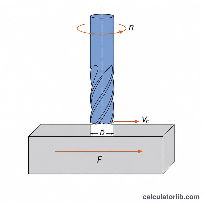
The formula explained
The cutting edge travels one circumference \(\pi D\) per revolution, so surface speed is circumference times RPM. Solving for RPM gives:
$$n = \frac{1000 \times v_c}{\pi \times D}$$where \(n\) = spindle speed in RPM, \(v_c\) = cutting speed in m/min, \(D\) = cutter diameter in mm, and the 1000 converts metres to millimetres. In imperial units the constant is 12 (inches per foot): \(n = 12\,\text{SFM} / (\pi D_{in})\). Feed rate then follows from chip load \(f_z\) and flute count \(z\):
$$v_f = n \times z \times f_z$$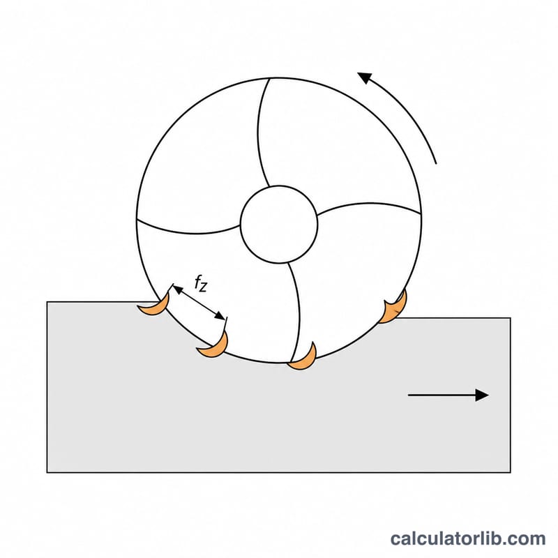
Worked example
A 12 mm four-flute carbide end mill, rated 120 m/min, run at 0.05 mm per tooth:
$$n = \frac{1000 \times 120}{\pi \times 12} = \frac{120000}{37.699} = 3183\ \text{RPM}$$$$v_f = 3183 \times 4 \times 0.05 = 636.6\ \text{mm/min}$$If your machine tops out below that RPM, the calculator clamps the spindle to the limit and reports the surface speed you actually achieve, which is what governs tool life and finish.
Cutting Speed and Chip Load Reference by Material and Tool
The two numbers this calculator needs from you are the cutting speed \(V_c\) (surface speed of the cutter periphery) and the feed per tooth \(f_z\) (chip load). The table below gives conservative, general-purpose starting points for solid end mills in dry-to-flood conditions. They are not taken from any national standard — carbide grade groups are described using the ISO 513 letter system (N for non-ferrous, P for steel, M for stainless, K for cast iron, S for heat-resistant alloys) purely as a naming convention. Always compare against the data sheet of the specific tool you are holding; a modern high-performance end mill may run at two to three times these speeds, and a worn or long-reach tool considerably less.
| Workpiece material | HSS / HSS-Co | Uncoated carbide | Coated carbide (TiAlN, AlCrN…) |
|---|---|---|---|
| Aluminium alloys (6061, 7075) | 70–150 m/min (230–490 SFM) | 200–500 m/min (660–1640 SFM) | 300–800 m/min (980–2620 SFM) |
| Mild / low-carbon steel (1018, S235) | 20–35 m/min (65–115 SFM) | 60–120 m/min (200–390 SFM) | 120–200 m/min (390–660 SFM) |
| Alloy & tool steel (4140, ~30 HRC) | 12–20 m/min (40–65 SFM) | 40–80 m/min (130–260 SFM) | 80–150 m/min (260–490 SFM) |
| Stainless steel 304 / 316 | 12–20 m/min (40–65 SFM) | 40–70 m/min (130–230 SFM) | 70–120 m/min (230–390 SFM) |
| Grey cast iron | 18–30 m/min (60–100 SFM) | 50–100 m/min (165–330 SFM) | 100–180 m/min (330–590 SFM) |
| Brass / bronze | 45–90 m/min (150–300 SFM) | 120–250 m/min (390–820 SFM) | 150–300 m/min (490–980 SFM) |
| Titanium Ti-6Al-4V | 8–12 m/min (26–40 SFM) | 20–40 m/min (65–130 SFM) | 30–60 m/min (100–200 SFM) |
| Plastics (acetal, ABS, nylon, PC) | 100–250 m/min (330–820 SFM) | 200–600 m/min (660–1970 SFM) | coating rarely needed; polished uncoated preferred |
| Workpiece material | HSS | Carbide (coated or uncoated) |
|---|---|---|
| Aluminium alloys | 0.05–0.10 mm/tooth (0.002–0.004 in) | 0.08–0.15 mm/tooth (0.003–0.006 in) |
| Mild / low-carbon steel | 0.03–0.06 mm/tooth (0.001–0.0025 in) | 0.05–0.10 mm/tooth (0.002–0.004 in) |
| Alloy & tool steel | 0.025–0.05 mm/tooth (0.001–0.002 in) | 0.04–0.08 mm/tooth (0.0015–0.003 in) |
| Stainless 304 / 316 | 0.025–0.05 mm/tooth (0.001–0.002 in) | 0.04–0.08 mm/tooth (0.0015–0.003 in) |
| Grey cast iron | 0.04–0.08 mm/tooth (0.0015–0.003 in) | 0.06–0.12 mm/tooth (0.0025–0.005 in) |
| Brass / bronze | 0.05–0.10 mm/tooth (0.002–0.004 in) | 0.08–0.15 mm/tooth (0.003–0.006 in) |
| Titanium Ti-6Al-4V | 0.02–0.04 mm/tooth (0.0008–0.0015 in) | 0.04–0.08 mm/tooth (0.0015–0.003 in) |
| Plastics | 0.05–0.12 mm/tooth (0.002–0.005 in) | 0.08–0.20 mm/tooth (0.003–0.008 in) |
How to use these ranges
- Chip load scales with cutter diameter. The \(f_z\) table above is written for a 10–12 mm cutter. As a rough guide, a 2–3 mm cutter takes roughly one third of those values (often 0.01–0.03 mm/tooth), a 6 mm cutter about half to two thirds, and a 20 mm or larger cutter 1.5–2 times them. A small end mill fed at large-cutter chip load simply snaps.
- Start at the low end of the speed range for long-reach tools, deep pockets, weak fixturing, low-power or belt-driven spindles, and manual machines; move toward the high end only with rigid setups, short tools and reliable coolant or air blast.
- Speed kills tools, feed makes chips. If the tool burns or wears fast, reduce \(V_c\) first. If chips are dust-like and the tool is rubbing rather than cutting, increase \(f_z\).
- Depth of cut is not in the RPM formula but limits what the ranges above will survive. Full-slot cuts (radial engagement \(a_e = D\)) generally need \(f_z\) reduced by 30–50% versus a light side-milling pass.
- Aluminium and plastics need chip evacuation, not just speed. Use 2–3 flutes so chips can clear; 4+ flutes in a soft material at high feed will pack the flutes and weld chips to the cutter.
These are general machining guidelines, not a specification for any particular tool, machine or safety code. Verify against your tool manufacturer's data and your machine's power and rigidity limits before cutting.
Key Terms and Variables
- Cutting speed, \(V_c\) (m/min; SFM = surface feet per minute)
- The tangential speed at which the cutting edge passes through the workpiece — the speed of a point on the cutter's outer circumference. This is the material-driven number: it is set by the workpiece/tool-material pair and coolant, not by the machine. \(V_c = \pi D n / 1000\) in metric.
- Spindle speed, \(n\) (RPM, rev/min)
- How fast the spindle turns. It is an output, derived from \(V_c\) and \(D\), and is capped by the machine: this calculator applies \(n = \min(1000 V_c / \pi D,\ n_{\max})\), so a small cutter on a 6000 RPM knee mill returns the machine limit rather than an impossible 20000 RPM.
- Cutter diameter, \(D\) (mm; in)
- The nominal outside diameter of the cutting portion of the tool — not the shank. For an indexable face mill it is the insert cutting-circle diameter, which is usually larger than the body diameter.
- Effective cutting diameter, \(D_{\mathrm{eff}}\) (mm; in)
- The diameter actually engaged in the cut when the full nominal diameter is not touching the work. Critical for ball-nose cutters at shallow axial depth \(a_p\): for \(a_p < D/2\),
Using \(D\) instead of \(D_{\mathrm{eff}}\) in the RPM formula makes a ball nose run far too slowly — the real surface speed at the small engaged radius collapses, and the tool rubs instead of cutting. For a 10 mm ball nose at \(a_p = 0.5\) mm, \(D_{\mathrm{eff}} = 2\sqrt{0.5 \times 9.5} = 4.36\) mm, less than half the nominal.
- Number of flutes / teeth, \(z\) (dimensionless)
- How many cutting edges pass the work per revolution. Typical: 2–3 for aluminium and plastics (chip room), 4 for general steel, 5–8+ for finishing and high-feed steel work. Flute count affects feed rate directly and cutting speed not at all.
- Feed per tooth / chip load, \(f_z\) (mm/tooth; in/tooth)
- The thickness of material each individual tooth removes per revolution — the true measure of how hard each edge is working. Too low causes rubbing, heat and rapid edge wear; too high causes chipping or tool breakage.
- Feed per revolution, \(f_n\) (mm/rev; IPR)
- How far the table advances in one spindle revolution: \(f_n = z \cdot f_z\). Useful for comparing tools with different flute counts on the same job.
- Table feed rate, \(v_f\) (mm/min; IPM)
- The linear speed programmed as the F word in G-code. It is the second output of this calculator: \(v_f = n \cdot z \cdot f_z\). Because it depends on \(n\), any RPM cap must be applied before the feed is computed, or the chip load will be far higher than intended.
- Radial depth of cut, \(a_e\) — also "stepover" or WOC (mm; in)
- How far the cutter is engaged sideways into the material, measured perpendicular to the feed direction. \(a_e = D\) is a full slot; \(a_e = 0.05D\) is a light finishing or trochoidal pass.
- Axial depth of cut, \(a_p\) — also DOC (mm; in)
- How deep the cutter is engaged along its axis, measured parallel to the tool axis. Together \(a_e\) and \(a_p\) set the material removal rate: \(\mathrm{MRR} = a_e \cdot a_p \cdot v_f\), and hence the spindle power and cutting forces.
- Chip thinning (radial)
- When radial engagement is less than half the diameter (\(a_e < D/2\)), each tooth's arc of contact is short and the maximum chip it cuts is thinner than the programmed \(f_z\):
To restore the intended chip thickness on a light radial pass, the programmed feed per tooth is increased by the inverse factor:
$$f_{z,\text{prog}} = f_z \cdot \frac{D}{2\sqrt{a_e (D - a_e)} }$$Example: a 12 mm cutter at \(a_e = 1.2\) mm (10% stepover) gives a factor of \(12 / (2\sqrt{1.2 \times 10.8}) = 12/7.2 = 1.67\), so 0.05 mm/tooth would be programmed as about 0.083 mm/tooth. Ignoring chip thinning is why light-stepover passes often wear tools faster than heavier ones — the edge rubs and generates heat instead of forming a chip.
- Climb vs conventional milling
- Climb milling (cutter rotation and feed in the same direction at the point of contact) starts each chip thick and ends thin; it gives better finish and tool life on rigid, backlash-free machines. Conventional milling is safer on machines with loose leadscrews. Neither changes the RPM calculation, but climb milling generally tolerates the upper end of the \(f_z\) ranges.
FAQ
Which diameter do I enter? The effective cutting diameter. For a plain end mill that is the nominal diameter; for a ball nose cutting shallow, the effective diameter at the depth of cut is smaller, so RPM should be higher.
Why is my computed RPM impossibly high? Small cutters demand very high spindle speeds. A 3 mm tool at 100 m/min needs over 10,000 RPM; if the machine cannot reach it, reduce feed per tooth accordingly and expect rubbing rather than clean chip formation.
Is chip load required? No. Leave it at zero if you only want spindle speed and surface speed; the feed rows simply read zero.