What this calculator does
The machining time calculator estimates how long a single cutting operation takes on a lathe, mill, or drill press. It works with metric shop units: length of cut in millimetres, feed per revolution in mm/rev, and spindle speed in revolutions per minute. Because the maths is pure kinematics, it applies to any machine tool anywhere in the world.
The formula explained
The tool first converts feed per revolution into a linear feed speed, then divides the distance the tool must travel by that speed:
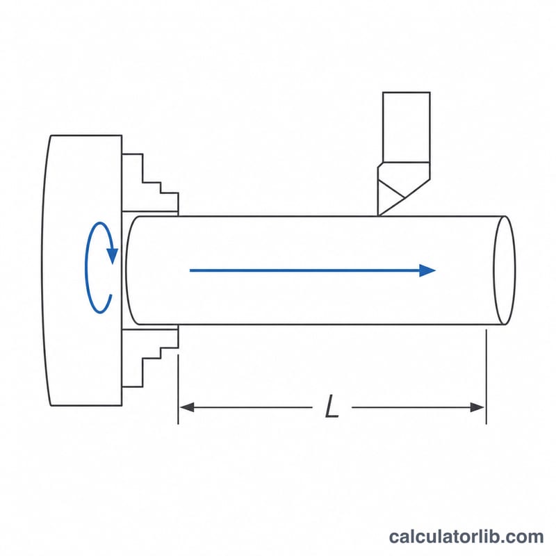
$$v_f = f \times N \qquad T = \frac{L \times n_p}{v_f}$$Here \(L\) = length of cut in mm (include tool approach and overrun), \(f\) = feed per revolution in mm/rev, \(N\) = spindle speed in RPM, \(n_p\) = number of passes, and \(T\) = cutting time in minutes. Note that time depends only on the product \(f \times N\): halving the feed and doubling the RPM leaves the time unchanged.
Worked example
Turning a shaft over a 250 mm length at 800 RPM with a feed of 0.15 mm/rev, in 3 roughing passes:
$$v_f = 0.15 \times 800 = 120\,\text{mm/min}$$$$T = \frac{250 \times 3}{120} = 6.25\,\text{min} = 375\,\text{s}$$The spindle turns \(800 \times 6.25 = 5000\) revolutions during the cut, a useful number when estimating insert wear per edge.
How to use it
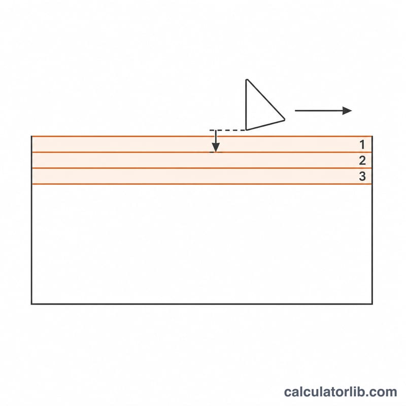
Measure the full travel of the tool, not just the finished feature length. Add roughly the tool diameter for a milling cut and 2-3 mm of approach plus overrun for turning, otherwise the estimate will be optimistic. Enter the feed value your CAM post or speed-and-feed chart gives, set the number of passes required to reach depth, and read the total time.
Machining Time Across Common Scenarios
All rows below use the same relationship the calculator applies, with lengths in millimetres and feed in millimetres per revolution (the metric/ISO convention; inch shops should convert first — see the conversion section):
$$T = \frac{L \times n_p}{f \times N} = \frac{L \times n_p}{v_f}, \qquad v_f = f \times N$$The length \(L\) is the travel of the tool, so it must already include approach and overrun, not just the finished feature length.
| Operation | L (mm) | f (mm/rev) | N (RPM) | Passes \(n_p\) | \(v_f = f \times N\) (mm/min) | T (min) | T (s) |
|---|---|---|---|---|---|---|---|
| Turning, medium carbon steel (roughing) | 250 | 0.15 | 800 | 3 | 120 | 6.25 | 375 |
| Turning, aluminium (single finishing pass) | 250 | 0.30 | 1600 | 1 | 480 | 0.52 | 31.3 |
| Drilling, through hole | 60 | 0.10 | 1200 | 1 | 120 | 0.50 | 30 |
| Face milling, slab pass | 400 | 0.50 | 2000 | 2 | 1000 | 0.80 | 48 |
Worked check on the first row, with every substitution shown:
$$v_f = 0.15\ \text{mm/rev} \times 800\ \text{rev/min} = 120\ \text{mm/min}$$$$T = \frac{250\ \text{mm} \times 3}{120\ \text{mm/min}} = \frac{750}{120} = 6.25\ \text{min} = 6.25 \times 60 = 375\ \text{s}$$Two observations follow from the table. First, doubling the feed and doubling the spindle speed (row 1 → row 2) quarters the time per pass — feed rate, not spindle speed alone, sets the clock. Second, the milling row uses \(f\) as feed per revolution; with a 4-tooth cutter that same 0.50 mm/rev corresponds to \(f_z = 0.125\) mm/tooth. Feed values here are illustrative combinations, not recommendations — always take the feed and speed from the tool manufacturer's data for your specific insert grade, workpiece material and machine rigidity.
Feed and Speed Unit Conversions
The calculator expects a consistent set of units: length of cut in mm, feed in mm/rev, spindle speed in RPM, and it returns minutes. Use the exact factors below to bring inch-system or per-tooth data into that form. The inch quantities (in/rev, in/min, SFM) are the customary US/imperial shop units; the mm and m/min quantities are the ISO metric convention.
| Convert | Relationship | Example |
|---|---|---|
| in/rev → mm/rev | \(f_{\text{mm}} = f_{\text{in}} \times 25.4\) (exact) | 0.006 in/rev × 25.4 = 0.1524 mm/rev |
| mm/rev → in/rev | \(f_{\text{in}} = f_{\text{mm}} \div 25.4\) | 0.25 mm/rev ÷ 25.4 = 0.00984 in/rev |
| in/min → mm/min | \(v_{f,\text{mm}} = v_{f,\text{in}} \times 25.4\) | 20 in/min × 25.4 = 508 mm/min |
| mm/min → in/min | \(v_{f,\text{in}} = v_{f,\text{mm}} \div 25.4\) | 1000 mm/min ÷ 25.4 = 39.37 in/min |
| Feed per tooth → feed per revolution | \(f = f_z \times z\) | 0.125 mm/tooth × 4 teeth = 0.50 mm/rev |
| Feed rate → feed per revolution | \(f = \dfrac{v_f}{N}\) | 1000 mm/min ÷ 2000 RPM = 0.50 mm/rev |
| Feed per revolution → feed rate | \(v_f = f \times N\) | 0.15 mm/rev × 800 RPM = 120 mm/min |
| Cutting speed → spindle speed | \(N = \dfrac{1000\,V_c}{\pi D}\), \(V_c\) in m/min, \(D\) in mm | \(N = \dfrac{1000 \times 200}{\pi \times 50} = 1273\) RPM |
| Spindle speed → cutting speed | \(V_c = \dfrac{\pi D N}{1000}\) | \(V_c = \dfrac{\pi \times 50 \times 1273}{1000} = 200\) m/min |
| SFM → m/min | \(V_c = \text{SFM} \times 0.3048\) (exact) | 400 SFM × 0.3048 = 121.9 m/min |
| m/min → SFM | \(\text{SFM} = V_c \div 0.3048 = V_c \times 3.2808\) | 150 m/min ÷ 0.3048 = 492 SFM |
| Minutes → seconds | \(t_s = T \times 60\) | 6.25 min × 60 = 375 s |
| Minutes → hours | \(t_h = T \div 60\) | 90 min ÷ 60 = 1.5 h |
Note on \(D\) in the cutting-speed formula: for turning it is the workpiece diameter at the cut, for drilling and milling it is the tool diameter. On a CNC lathe running constant surface speed (G96), \(N\) changes continuously as the diameter changes, so a single-\(N\) time estimate is only valid for cuts at a roughly constant diameter; facing and parting off need to be handled separately.
Key Terms and Variables
Symbols follow common ISO/metric machining practice; the equivalent inch-system units are given where shops differ.
| Term | Symbol | Unit | Meaning |
|---|---|---|---|
| Length of cut | \(L\) | mm (in) | Total distance the tool feeds along the cut direction in one pass, including approach and overrun — not just the finished feature length. |
| Feed per revolution | \(f\) | mm/rev (in/rev) | Tool advance per one spindle revolution. The native feed unit for turning and drilling. |
| Feed per tooth | \(f_z\) | mm/tooth | Chip load on each cutting edge in milling. Converted with \(f = f_z \times z\). |
| Number of teeth | \(z\) | — | Effective cutting edges on the milling cutter (or flutes on an end mill). |
| Feed rate | \(v_f\) | mm/min (in/min) | Linear table or slide speed, \(v_f = f \times N = f_z \times z \times N\). This is what the machine's F word commands in G94 mode. |
| Spindle speed | \(N\) | RPM (rev/min) | Rotational speed of the spindle (workpiece in turning, tool in milling and drilling). |
| Cutting speed | \(V_c\) | m/min (SFM) | Surface speed at the cutting edge, \(V_c = \pi D N / 1000\). Set by tool grade and workpiece material; it is what you look up first, then solve for \(N\). |
| Depth of cut | \(a_p\) | mm | Thickness of material removed per pass, measured perpendicular to the feed direction. It does not enter the time formula directly, but it determines how many passes are needed. |
| Number of passes | \(n_p\) | — | How many times the tool traverses \(L\), typically \(n_p \approx\) total stock to remove ÷ \(a_p\), rounded up. |
| Cutting time | \(T\) | min (s) | Time the tool is actually engaged and feeding: \(T = L \, n_p / (f N)\). Also called machining time or in-cut time. |
Approach and overrun. Approach is the extra travel before the edge reaches full engagement (for a drill with a 118° point, the point length is roughly \(0.3 \times D\); for a face mill it is the lead-in needed for the cutter radius). Overrun is the travel beyond the far side of the workpiece so the feature is complete and the tool exits cleanly. Both are added to the feature length to obtain \(L\). Omitting them is the single most common reason a calculated time comes out lower than the machine actually takes on short cuts.
Cutting time vs floor-to-floor time. The calculator returns cutting time only. Floor-to-floor (or cycle) time additionally includes rapid moves, tool changes, spindle acceleration and dwell, part loading and unloading, clamping, deburring and in-process gauging. For short parts these non-cutting elements can exceed the cutting time itself, so quote work should sum the cutting times of all operations and then add measured or estimated handling time rather than treating \(T\) as the cycle time.
FAQ
Does this include setup and tool change time? No. The result is pure cutting time. Add setup, loading, tool changes, and inspection separately to obtain a floor-to-floor cycle time.
My feed is given in mm/min, not mm/rev. Divide it by the spindle speed to get feed per revolution, or enter feed per revolution as your mm/min value divided by RPM.
What about feed per tooth on a milling cutter? Multiply feed per tooth by the number of teeth to get feed per revolution, then enter that figure.