What is a multiple-gear gear ratio?
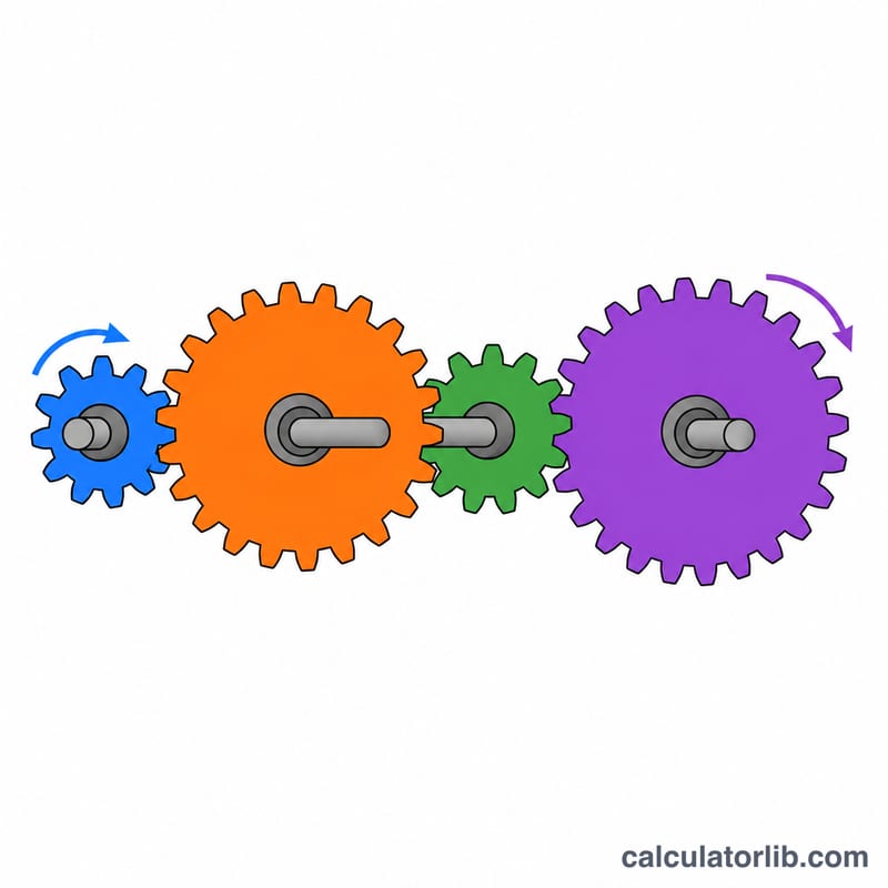
When power passes through several pairs of meshing gears, each pair changes speed and torque. The overall gear ratio tells you how many times the input shaft turns for each single turn of the output shaft. This calculator handles compound trains of up to four stages, where each stage has a driver gear and a driven gear.
How to use the calculator
For each stage, enter the number of teeth on the driver gear (the one receiving power) and on the driven gear (the one it meshes with). Leave optional stages empty or at zero if your train is shorter. Enter the input speed in RPM to get the output speed as well.
The formula explained
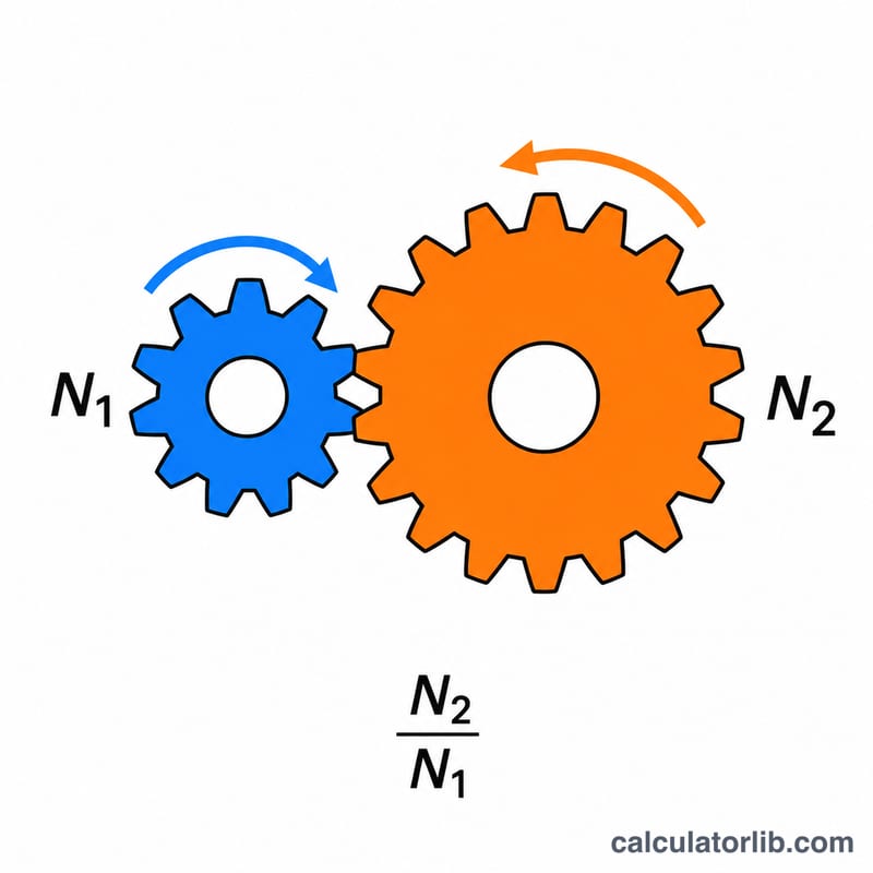
The overall ratio is the product of the individual stage ratios:
$$i_{total} = \frac{N_{driven,1}}{N_{driver,1}} \times \frac{N_{driven,2}}{N_{driver,2}} \times \cdots$$Here \(N\) is the tooth count of a gear. Output speed is \(\omega_{out} = \omega_{in} / i_{total}\), and ideal output torque is the input torque multiplied by \(i_{total}\), ignoring friction losses. Each external mesh reverses rotation, so an even number of stages gives the same direction as the input and an odd number reverses it.
Worked example
Stage 1 uses a 20-tooth driver and a 40-tooth driven gear; stage 2 uses an 18-tooth driver and a 54-tooth driven gear. The input runs at 1800 RPM.
$$i_{total} = \frac{40}{20} \times \frac{54}{18} = 2 \times 3 = 6$$$$\omega_{out} = \frac{1800}{6} = 300\,\text{RPM}$$The output turns six times slower and, ideally, delivers six times the torque.
Typical Gear Ratios per Stage
The figures below are general engineering rules of thumb for external gears. Exact limits depend on the design standard, materials, load and manufacturer.
| Item | Typical value |
|---|---|
| Single-stage spur gear ratio | about 1:1 to 6:1 (commonly up to 10:1 at the maximum) |
| Efficiency per mesh, spur gears | about 95–99% |
| Efficiency per mesh, helical gears | about 94–98% |
| Efficiency, worm gears | about 40–90% (falls as the lead angle gets smaller) |
| Minimum pinion teeth, 20° pressure angle | about 17 teeth (to avoid undercut with standard full-depth teeth) |
| 2 stages overall ratio | roughly 10:1 to 50:1 |
| 3 stages overall ratio | roughly 30:1 to 200:1 |
| 4 stages overall ratio | roughly 100:1 to 1000:1 or more |
Why use compound stages?
A single pair of gears becomes impractical at high ratios. To get a ratio of 30:1 from one pair, the pinion would need to be tiny (and so undercut or weak) or the large gear would be huge. Splitting the ratio across stages keeps each pinion above the minimum tooth count and keeps the gearbox compact. The overall ratio is the product of the stage ratios, so three stages of 3:1 give 27:1.
Efficiency adds up
Every mesh loses some power, and the losses multiply. Three spur stages at 97% each give \(0.97^3 \approx 0.913\), or about 91% overall. Real output torque is therefore somewhat lower than the ideal value this calculator reports.
Comparing Example Gear Train Configurations
All rows use an input speed of 1800 RPM. Each stage is a pair of external spur gears, with the driven gear of one stage sharing a shaft with the driver of the next. There are no idlers. Ideal torque multiplier equals the total ratio and ignores friction losses. Each external mesh reverses rotation, so an odd number of stages gives reversed output and an even number gives the same direction.
| Configuration (driver:driven teeth) | Calculation | Total ratio | Output RPM | Ideal torque multiplier | Rotation |
|---|---|---|---|---|---|
| 1 stage: 20:60 | \(60/20\) | 3:1 | 600 | 3× | Reversed |
| 2 stages: 20:40, 18:54 | \(2 \cdot 3\) | 6:1 | 300 | 6× | Same |
| 3 stages: 15:45 ×3 | \(3 \cdot 3 \cdot 3\) | 27:1 | 66.7 | 27× | Reversed |
| 4 stages: 20:40, 20:50, 18:54, 15:60 | \(2 \cdot 2.5 \cdot 3 \cdot 4\) | 60:1 | 30 | 60× | Same |
Output RPM is \(1800 / i\). For the 3-stage row, \(1800 / 27 \approx 66.7\) RPM. Torque goes up by the same factor that speed goes down, minus losses.
FAQ
Does an idler gear change the ratio?
No. An idler gear that sits between a driver and a driven gear only reverses direction; its tooth count cancels out of the ratio.
What does a ratio below 1 mean?
The output turns faster than the input (overdrive), at the cost of reduced torque.
Are losses included?
No. Real gear meshes are typically 95 to 99 percent efficient per stage, so actual output torque is slightly lower than the ideal value shown.