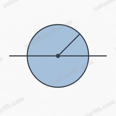
What is Mohr's Circle?
Mohr's Circle is a two-dimensional graphical representation used in mechanics to visualize the state of stress at a point in a material. It allows engineers to determine principal stresses, maximum shear stresses, and the orientation of principal planes from a known stress state. This powerful tool was developed by German civil engineer Otto Mohr and is extensively used in mechanical engineering, civil engineering, and materials science.
When to Use Mohr's Circle Calculator
A Mohr's Circle Calculator is valuable in the following scenarios:
- Analyzing stress distribution in structural components under complex loading conditions
- Determining critical stress points that might lead to material failure in mechanical parts
- Designing components that need to withstand specific stress states in multiple directions

Examples
Example 1: Analyzing Stress in a Beam
Calculate the principal stresses and maximum shear stress for a point in a beam with normal stresses \(\sigma_x = 80\ \text{MPa}\), \(\sigma_y = 20\ \text{MPa}\), and shear stress \(\tau_{xy} = 30\ \text{MPa}\).
| Parameter | Value |
|---|---|
| Normal stress \(\sigma_x\) | 80 MPa |
| Normal stress \(\sigma_y\) | 20 MPa |
| Shear stress \(\tau_{xy}\) | 30 MPa |
| Center of Mohr's Circle (\(\sigma_{avg}\)) | 50 MPa |
| Radius of Mohr's Circle (\(R\)) | 36.06 MPa |
| Principal stress \(\sigma_1\) | 86.06 MPa |
| Principal stress \(\sigma_2\) | 13.94 MPa |
| Maximum shear stress \(\tau_{max}\) | 36.06 MPa |
| Angle to principal plane \(\theta_p\) | 22.5 degrees |
Example 2: Stress Analysis in a Pressure Vessel
For a point on a pressure vessel with normal stresses \(\sigma_x = 120\ \text{MPa}\), \(\sigma_y = 60\ \text{MPa}\), and shear stress \(\tau_{xy} = 40\ \text{MPa}\), determine the principal stresses and maximum shear stress.
| Parameter | Value |
|---|---|
| Normal stress \(\sigma_x\) | 120 MPa |
| Normal stress \(\sigma_y\) | 60 MPa |
| Shear stress \(\tau_{xy}\) | 40 MPa |
| Center of Mohr's Circle (\(\sigma_{avg}\)) | 90 MPa |
| Radius of Mohr's Circle (\(R\)) | 50 MPa |
| Principal stress \(\sigma_1\) | 140 MPa |
| Principal stress \(\sigma_2\) | 40 MPa |
| Maximum shear stress \(\tau_{max}\) | 50 MPa |
| Angle to principal plane \(\theta_p\) | 26.57 degrees |
Example 3: Pure Shear Analysis
Analyze a state of pure shear where \(\sigma_x = 0\ \text{MPa}\), \(\sigma_y = 0\ \text{MPa}\), and \(\tau_{xy} = 50\ \text{MPa}\).
| Parameter | Value |
|---|---|
| Normal stress \(\sigma_x\) | 0 MPa |
| Normal stress \(\sigma_y\) | 0 MPa |
| Shear stress \(\tau_{xy}\) | 50 MPa |
| Center of Mohr's Circle (\(\sigma_{avg}\)) | 0 MPa |
| Radius of Mohr's Circle (\(R\)) | 50 MPa |
| Principal stress \(\sigma_1\) | 50 MPa |
| Principal stress \(\sigma_2\) | -50 MPa |
| Maximum shear stress \(\tau_{max}\) | 50 MPa |
| Angle to principal plane \(\theta_p\) | 45 degrees |
Common Stress States and Mohr's Circle Characteristics
| Stress State | Characteristics | Mohr's Circle Properties |
|---|---|---|
| Uniaxial Tension | \(\sigma_x > 0,\ \sigma_y = 0,\ \tau_{xy} = 0\) | Center at \(\sigma_x/2\), Radius \(= \sigma_x/2\) |
| Pure Shear | \(\sigma_x = 0,\ \sigma_y = 0,\ \tau_{xy} \neq 0\) | Center at origin, Radius \(= \tau_{xy}\) |
| Biaxial Tension | \(\sigma_x > 0,\ \sigma_y > 0,\ \tau_{xy} = 0\) | Center at \((\sigma_x+\sigma_y)/2\), Radius \(= |\sigma_x-\sigma_y|/2\) |
| Hydrostatic Stress | \(\sigma_x = \sigma_y,\ \tau_{xy} = 0\) | Reduces to a point (no shear) |
| Complex Stress | \(\sigma_x \neq \sigma_y,\ \tau_{xy} \neq 0\) | Center at \((\sigma_x+\sigma_y)/2\), Radius as per formula |

Related Calculators
For more stress and structural analysis tools, you might find these calculators useful:
- Pythagorean Theorem Calculator - For basic geometric calculations
- Friction Calculator - For analyzing forces in mechanical systems
- Potential Energy Calculator - For energy analysis in structures
Key Terms and Variables Explained
| Term (symbol) | Typical units | Definition |
|---|---|---|
| Normal stress (\(\sigma_x\), \(\sigma_y\)) | MPa or N/mm² (SI); psi or ksi (US customary) | Force per unit area acting perpendicular to a face of the element. \(\sigma_x\) acts on the face whose outward normal points along x; \(\sigma_y\) on the face normal to y. |
| Shear stress (\(\tau_{xy}\)) | MPa, psi | Force per unit area acting parallel (tangential) to a face. Moment equilibrium requires \(\tau_{xy} = \tau_{yx}\), so a single value describes the in-plane shear. |
| Principal stresses (\(\sigma_1\), \(\sigma_2\)) | MPa, psi | The extreme normal stresses, acting on the two mutually perpendicular principal planes on which the shear stress is exactly zero. Convention: \(\sigma_1 \ge \sigma_2\). They are the intersections of the circle with the horizontal axis. |
| Maximum in-plane shear stress (\(\tau_{max}\)) | MPa, psi | The largest shear stress on any plane perpendicular to the plane of analysis; numerically equal to the circle radius, \(\tau_{max} = R = (\sigma_1 - \sigma_2)/2\). |
| Average / mean normal stress (\(\sigma_{avg}\)) | MPa, psi | \(\sigma_{avg} = (\sigma_x + \sigma_y)/2 = (\sigma_1 + \sigma_2)/2\). It is the horizontal coordinate of the circle's centre and is invariant under rotation of the axes. |
| Radius (\(R\)) | MPa, psi | \(R = \sqrt{\left((\sigma_x - \sigma_y)/2\right)^{2} + \tau_{xy}^{2}}\). A measure of the deviatoric (shape-changing) part of the in-plane stress state. |
| Principal plane angle (\(\theta_p\)) | degrees or radians | Rotation from the x-axis to the direction of \(\sigma_1\), \(\theta_p = \tfrac{1}{2}\tan^{-1}\!\left(2\tau_{xy}/(\sigma_x-\sigma_y)\right)\). The two principal directions are \(90^\circ\) apart. |
| Plane of maximum shear (\(\theta_s\)) | degrees | \(\theta_s = \theta_p \pm 45^\circ\). On these planes the shear reaches \(\tau_{max}\) and the normal stress equals \(\sigma_{avg}\) — maximum shear planes are never shear-only unless \(\sigma_{avg}=0\). |
| Doubled angle (\(2\theta\)) | degrees | Angles measured around Mohr's circle are twice the corresponding physical rotation of the element, and in the same rotational sense. |
Sign convention
The convention used here — and the one this calculator expects — is the standard mechanics-of-materials one: tensile normal stress is positive, compressive normal stress is negative (enter a 40 MPa compression as \(-40\)). For shear, a positive \(\tau_{xy}\) is one that acts on the positive x-face in the positive y-direction; on the circle this is commonly plotted so that shear tending to rotate the element counterclockwise is treated as positive in the transformation equations, while many textbooks plot the vertical axis inverted so the circle rotation matches the element rotation. Different books flip the plotted sign of the shear axis; this changes only the picture's mirror image, never the magnitudes of \(\sigma_1\), \(\sigma_2\) or \(\tau_{max}\). Be consistent within one problem.
Plane stress vs. plane strain
Plane stress assumes all stress components on the out-of-plane face vanish (\(\sigma_z = \tau_{xz} = \tau_{yz} = 0\)) — a good model for thin plates, sheet metal, shells and free surfaces, which is why surface stresses from strain gauges are usually treated this way. Plane strain assumes zero out-of-plane strain instead (\(\varepsilon_z = 0\)), which is typical of long prismatic bodies such as dams, tunnels, thick-walled pipes or a long roller. In plane strain \(\sigma_z = \nu(\sigma_x + \sigma_y) \ne 0\), where \(\nu\) is Poisson's ratio; the in-plane circle is identical, but the third principal stress is not zero. This calculator solves the in-plane circle, which is the same construction in both cases.
Named stress states
- Uniaxial stress — e.g. \(\sigma_x \ne 0\), \(\sigma_y = \tau_{xy} = 0\) (a simple tension bar). The circle passes through the origin, with centre \(\sigma_x/2\) and radius \(|\sigma_x|/2\), so \(\tau_{max} = |\sigma_x|/2\) at \(45^\circ\).
- Pure shear — \(\sigma_x = \sigma_y = 0\), \(\tau_{xy} \ne 0\) (a shaft in torsion). The circle is centred on the origin, and \(\sigma_1 = +|\tau_{xy}|\), \(\sigma_2 = -|\tau_{xy}|\) at \(45^\circ\) to the axis — which is why brittle shafts in torsion fracture on a helical \(45^\circ\) surface.
- Hydrostatic / equal-biaxial state — \(\sigma_x = \sigma_y\) with \(\tau_{xy} = 0\). The circle degenerates to a single point (\(R = 0\)): every plane carries the same normal stress and no shear at all.
Interpreting Your Mohr's Circle Results
What each output tells you
\(\sigma_1\) — the major principal stress. This is the largest normal stress acting at the point, and if positive it is the largest tensile stress on any plane through that point. It is the number you compare against the material's tensile strength: the yield strength \(\sigma_y\) (often written \(S_y\) or \(f_y\)) for ductile design, or the ultimate tensile strength for brittle materials, where the maximum-normal-stress criterion is more appropriate. Continuing the Example 1 numbers (\(\sigma_x=80\), \(\sigma_y=20\), \(\tau_{xy}=30\) MPa), \(\sigma_1 = 92.43\) MPa; against a material with a 250 MPa yield strength this is a factor of safety of about \(250/92.43 \approx 2.7\) on that criterion alone.
The sign of \(\sigma_2\). A positive \(\sigma_2\) means the element is in biaxial tension in the plane; a negative \(\sigma_2\) means one principal direction is in compression while the other is in tension, which widens the circle relative to the origin and generally makes shear-based failure criteria more critical. This matters for materials that behave very differently in tension and compression, such as concrete, cast iron, rock and most ceramics.
\(\tau_{max} = R\). The radius is the maximum in-plane shear stress. Under the maximum shear stress (Tresca) criterion, yielding of a ductile metal is predicted when the maximum shear reaches half the yield strength measured in a tension test — equivalently when
$$2\tau_{max} = \sigma_1 - \sigma_3 \ge \sigma_{yield}$$For Example 1 the in-plane value is \(\tau_{max} = 42.43\) MPa, so \(2\tau_{max} = 84.85\) MPa — well below a 250 MPa yield strength.
Don't forget the third principal stress
In plane stress the out-of-plane principal stress is \(\sigma_3 = 0\), and it must still be included when ranking the three principal stresses. The absolute maximum shear stress is half the difference between the largest and smallest of \(\{\sigma_1, \sigma_2, 0\}\), which is not always the in-plane value the circle shows. In Example 1 both in-plane principal stresses are tensile, so
$$\tau_{abs,max} = \frac{\sigma_1 - \sigma_3}{2} = \frac{92.43 - 0}{2} = 46.21\ \text{MPa} \;>\; 42.43\ \text{MPa}$$Using the in-plane figure alone would under-predict the shear by about 9% here. When \(\sigma_1\) and \(\sigma_2\) have opposite signs, the in-plane circle is the largest of the three circles and the two values agree.
The von Mises alternative
For ductile metals the distortion-energy (von Mises) criterion usually matches test data more closely than Tresca and is slightly less conservative. In plane stress the equivalent stress is
$$\sigma_{vm} = \sqrt{\sigma_1^{2} - \sigma_1\sigma_2 + \sigma_2^{2}}$$and yielding is predicted when \(\sigma_{vm} \ge \sigma_{yield}\). For Example 1, \(\sigma_{vm} = \sqrt{92.43^{2} - (92.43)(7.57) + 7.57^{2}} = \sqrt{8542.6 - 699.9 + 57.3} \approx 88.9\) MPa.
Reading the geometry of the circle
- Centre position (\(\sigma_{avg}\)) is the mean in-plane normal stress — the hydrostatic-like part that shifts the whole circle left (compression) or right (tension) without changing its size. Classical metal-plasticity criteria are insensitive to this shift; brittle and geotechnical materials are not.
- Radius (\(R\)) is the intensity of shear/distortion. A bigger circle means a more severe deviatoric state at the same mean stress.
- A circle centred on the origin (\(\sigma_{avg}=0\), so \(\sigma_1 = -\sigma_2\)) is pure shear. For instance \(\sigma_x = \sigma_y = 0\) with \(\tau_{xy} = 40\) MPa gives \(R=40\) MPa and \(\sigma_1 = \) 40 MPa in tension with \(\sigma_2 = -40\) MPa in compression, both at \(45^\circ\) to the shear directions.
- A zero-radius circle (a single point, \(\sigma_x = \sigma_y\), \(\tau_{xy} = 0\)) is an equal-biaxial or hydrostatic state: every plane through the point carries the same normal stress and no shear stress at all, so there is no preferred failure plane from shear.
- Points at the top and bottom of the circle also carry a normal stress equal to \(\sigma_{avg}\) — the planes of maximum shear are not shear-only unless the circle is centred on the origin.
Limits of this analysis
Mohr's circle is an exact consequence of equilibrium and applies to any 2-D stress state, but the interpretation above assumes linear-elastic, homogeneous, isotropic material behaviour, small deformations, and stresses evaluated at a single point. It does not account for stress concentrations at holes, notches and welds; residual or thermal stresses; anisotropy in composites, timber or rolled products; buckling and other stability limits; fatigue under cyclic loading; creep; or fracture from pre-existing cracks. Results are engineering information only, not a substitute for verification against the governing design code for your jurisdiction and material — for example Eurocode 3 (EN 1993) in the EU, AISC 360 in the United States, or the relevant ASME/API pressure-equipment rules — and any load-bearing design should be checked by a qualified engineer with appropriate partial safety factors or allowable-stress margins.