
What Is a Bolt Hole Circle Calculator?
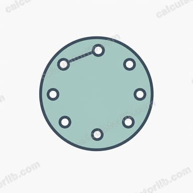
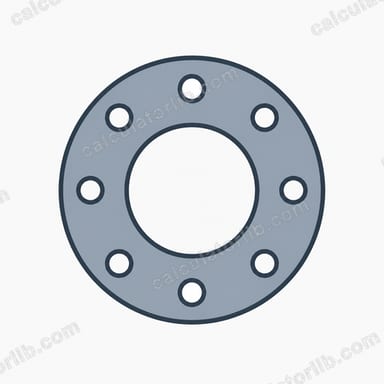
A Bolt Hole Circle (BHC) — also called a Pitch Circle Diameter (PCD) pattern — is a set of holes spaced evenly around an imaginary circle. This calculator takes the circle diameter, the number of holes, and a starting angle, then computes the exact X/Y coordinates and the angular position of every hole. It's a universal tool for engineers, machinists, and DIY fabricators worldwide, useful for flanges, wheel hubs, gear blanks, motor mounts, and any part where holes must sit on a common circle.
How to Use It
- Circle diameter (PCD): Enter the diameter of the circle the hole centers sit on, in mm or inches.
- Number of holes: Enter how many holes to space around the circle.
- Start angle: Set the angle of the first hole (0° is commonly to the right, or measure from the 12 o'clock position depending on your convention).
The calculator returns each hole's angle and its X/Y coordinates relative to the circle center, ready for layout marking or programming into a CNC machine.
The Formula Explained
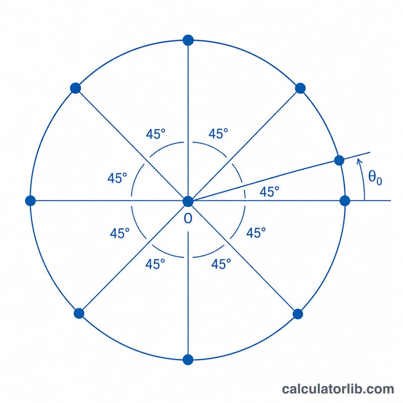
Holes are spaced equally, so the angle between adjacent holes is:
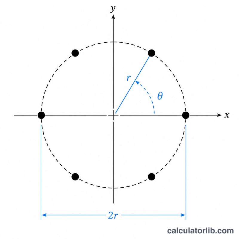
$$\left( x_i,\; y_i \right) = \left( r\cos\theta_i,\; r\sin\theta_i \right)$$
$$\text{where}\quad \left\{ \begin{aligned} r &= \dfrac{\text{Diameter}}{2} \\ \theta_i &= \text{Start Angle} + i \cdot \dfrac{360^{\circ}}{\text{Holes}} \\ i &= 0,\,1,\,\dots,\,\text{Holes}-1 \end{aligned} \right.$$
- Angle step \(= 360° \div\) number of holes
- Angle of hole \(n =\) start angle \(+\, (n - 1) \times\) step
- \(X = (\text{PCD} \div 2) \times \cos(\text{angle})\)
- \(Y = (\text{PCD} \div 2) \times \sin(\text{angle})\)
The radius is simply half the PCD. Trigonometry converts each hole's angle into a Cartesian position measured from the center of the pattern.
Worked Example
Suppose you need 6 holes on a 100 mm PCD, starting at 0°. The step is \(360 \div 6 = 60°\), so holes fall at 0°, 60°, 120°, 180°, 240°, and 300°. The radius is 50 mm. The first hole sits at \(X = 50 \times \cos(0°) = 50\), \(Y = 50 \times \sin(0°) = 0\). The second is at \(X = 50 \times \cos(60°) = 25\), \(Y = 50 \times \sin(60°) \approx 43.3\), and so on around the circle.
Common Standard Bolt Hole Circle Patterns
A bolt hole circle (BHC), also called a bolt circle diameter (PCD, pitch circle diameter), describes a set of holes evenly spaced around a circle. The table below lists widely-used standard patterns. Automotive wheel PCDs are quoted as (number of holes) × (PCD in mm), while flange bolt circles follow piping standards such as ASME B16.5.
| Pattern | PCD | Holes | Angle Step | Typical Application |
|---|---|---|---|---|
| 4 × 100 | 100 mm | 4 | 90° | Small/compact cars (e.g. economy hatchbacks) |
| 4 × 114.3 | 114.3 mm | 4 | 90° | Older sedans, light vehicles |
| 5 × 100 | 100 mm | 5 | 72° | Many compact and sport compacts |
| 5 × 114.3 | 114.3 mm | 5 | 72° | Very common passenger car / crossover PCD |
| 5 × 120 | 120 mm | 5 | 72° | BMW and several larger sedans |
| 6 × 139.7 | 139.7 mm | 6 | 60° | Pickup trucks and SUVs |
| 8 × 165.1 | 165.1 mm | 8 | 45° | Heavy-duty trucks |
| NPS 2" Class 150 flange | 120.7 mm (4.75") | 4 | 90° | ASME B16.5 pipe flange |
| NPS 4" Class 150 flange | 190.5 mm (7.5") | 8 | 45° | ASME B16.5 pipe flange |
| NPS 6" Class 150 flange | 241.3 mm (9.5") | 8 | 45° | ASME B16.5 pipe flange |
The angle step between adjacent holes is simply \(360^\circ / n\), where \(n\) is the number of holes. For example, a 5-hole pattern has a step of \(360^\circ/5 = 72^\circ\), and an 8-hole pattern steps every \(360^\circ/8 = 45^\circ\).
Practical Layout & Machining Tips
- Confirm the start-angle convention. This calculator measures \(0^\circ\) along the positive X axis (3 o'clock) and rotates counter-clockwise. If your drawing references the 12 o'clock (top) position, enter a start angle of \(90^\circ\); for clockwise patterns, negate the step or mirror the Y values.
- Match the origin to your CNC zero. The computed X/Y values are relative to the bolt circle center. Set your machine's work coordinate system (G54 part zero) at that center, or add the center offset to every coordinate so signs and quadrants are correct before cutting.
- Don't confuse hole diameter with PCD. The PCD locates the centers of the holes, not their edges. Choose the drill or end mill by the fastener clearance separately, and leave material for the hole diameter when planning edge distances.
- Center-drill and deburr. Spot or center-drill each location first so the drill doesn't wander off the true position, then deburr both faces. On flanges, burrs prevent proper gasket seating.
- Verify the PCD by measurement before drilling. For an even number of holes, the PCD equals the center-to-center distance of two opposite holes. For odd patterns (e.g. 5 holes), measure from one hole center to the midpoint between the two opposite holes, or use a chord-and-radius relation to back-calculate the circle. Always confirm against the mating part.
- Check the chord (hole-to-hole) spacing. Adjacent-hole spacing is a good independent cross-check: it equals \(2r\sin(180^\circ/n)\). Confirming this distance with calipers catches data-entry or unit errors before metal is removed.
These are general layout guidelines; always defer to the controlling engineering drawing, fastener specification, or applicable standard (e.g. ASME B16.5) for tolerances and final dimensions.
FAQ
What's the difference between PCD and bolt circle diameter? They mean the same thing — the diameter of the circle passing through all hole centers.
Where is 0° measured from? This calculator uses 0° pointing right (the positive X axis), with angles increasing counter-clockwise. Adjust the start angle to match your drawing.
Can I use inches? Yes. The coordinates come out in whatever unit you enter for the diameter.