What is impedance?
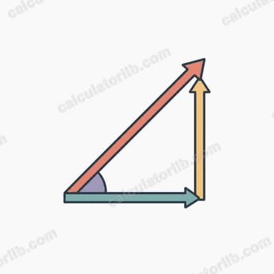
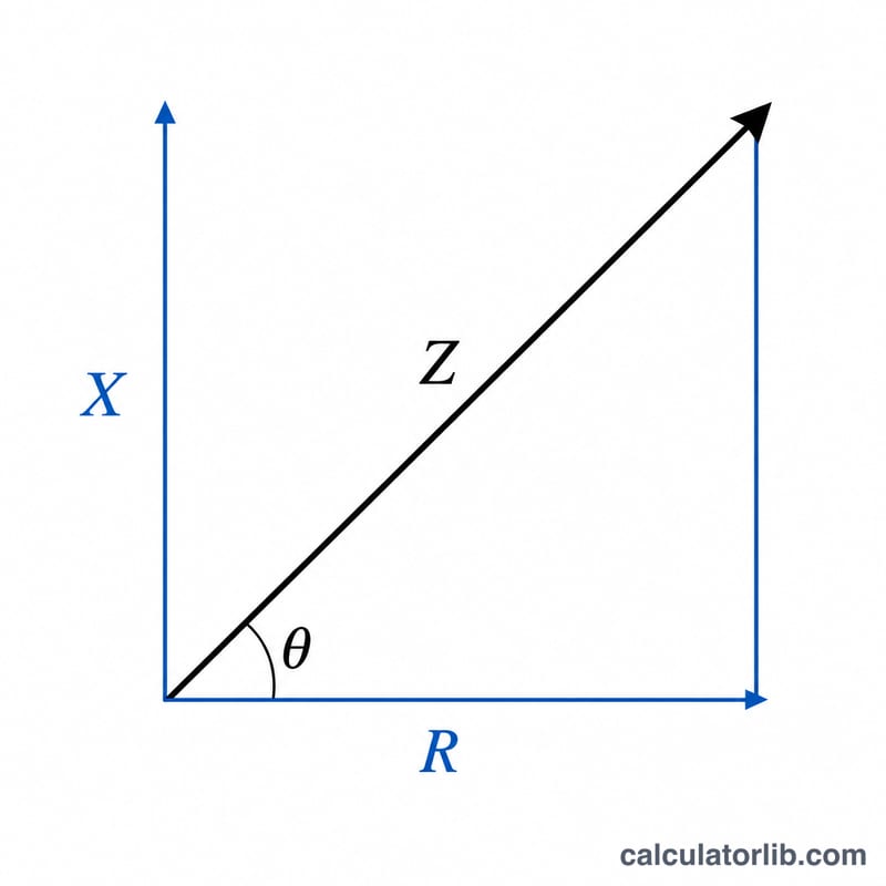
Impedance (Z) is the total opposition that a circuit presents to alternating current (AC). It combines the resistance (R), which dissipates energy, with the reactance (X), which stores and releases energy in inductors and capacitors. Because resistance and reactance act at right angles to each other in the complex plane, you cannot simply add them — instead you combine them as the hypotenuse of a right triangle.
How to use this calculator
Enter the resistance R in ohms and the net reactance X in ohms, then read off the impedance magnitude Z and the phase angle θ. The net reactance is the inductive reactance minus the capacitive reactance: \(X = X_{L} - X_{C}\). A positive X means the circuit is inductive; a negative X means it is capacitive. Either sign gives the same magnitude of Z because the term is squared, but the phase angle keeps the sign.
The formula explained
The impedance magnitude is given by $$Z = \sqrt{\text{R}^{2} + \text{X}^{2}}$$ The phase angle is $$\theta = \arctan\!\left(\frac{\text{X}}{\text{R}}\right) \times \frac{180}{\pi}$$ measured in degrees, telling you how far the current lags (inductive) or leads (capacitive) the voltage.
Worked example
Suppose R = 3 Ω and X = 4 Ω. Then $$Z = \sqrt{3^{2} + 4^{2}} = \sqrt{9 + 16} = \sqrt{25} = 5\ \Omega$$ The phase angle is \(\theta = \arctan(4 / 3) \approx 53.13°\), so the current lags the voltage by about 53 degrees.
Interpreting Your Impedance Result
The calculator returns the impedance magnitude \(Z\) in ohms (Ω) and the phase angle \(\theta\) in degrees, using:
$$Z = \sqrt{R^2 + X^2}, \qquad \theta = \arctan\left(\frac{X}{R}\right)$$
Phase angle ranges
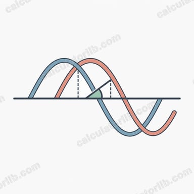
- θ = 0°: purely resistive (X = 0). Voltage and current are in phase.
- 0° to +90°: inductive (X > 0). Current lags voltage.
- −90° to 0°: capacitive (X < 0). Current leads voltage.
- ±90°: pure reactance (R = 0), such as an ideal inductor (+90°) or ideal capacitor (−90°).
The larger the ratio \(|X|/R\), the closer \(\theta\) moves toward ±90°. When \(R\) dominates, \(\theta\) stays near 0°.
What the numbers tell you
- \(Z \ge R\) and \(Z \ge |X|\) always, because the two components add at right angles (as a vector sum), not directly.
- Z in ohms sets the current for a given voltage: \(I = V/Z\). A higher Z means less current.
- The power factor is \(\cos\theta = R/Z\). A value near 1 means most of the apparent power does real work.
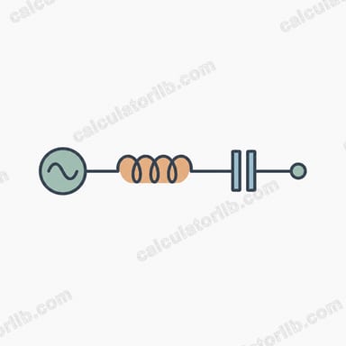
- In a series RLC circuit, resonance occurs when \(X_L = X_C\), so net \(X = 0\) and \(Z = R\). This is the minimum impedance of the circuit, and the current is at its maximum.
Reactance Formulas for Inductors and Capacitors
| Quantity | Formula / Value | Units and notes |
|---|---|---|
| Inductive reactance | \(X_L = 2\pi f L\) | Ω; f in hertz (Hz), L in henries (H) |
| Capacitive reactance | \(X_C = \dfrac{1}{2\pi f C}\) | Ω; f in Hz, C in farads (F) |
| Net reactance (series L and C) | \(X = X_L - X_C\) | Positive = inductive, negative = capacitive |
| Resistor | \(X = 0\) | Impedance equals R |
| Ideal inductor | \(\theta = +90^\circ\) | Current lags voltage |
| Ideal capacitor | \(\theta = -90^\circ\) | Current leads voltage |
Frequency dependence: \(X_L\) rises in proportion to frequency, so an inductor passes low frequencies more easily. \(X_C\) falls as frequency rises, so a capacitor passes high frequencies more easily. Compute net \(X = X_L - X_C\) first, then enter it with R into the calculator (use a negative value for a net capacitive reactance).
Impedance for Different R and X Combinations
| R (Ω) | X (Ω) | Z (Ω) | θ | Circuit type |
|---|---|---|---|---|
| 10 | 0 | 10 | 0° | Purely resistive |
| 10 | 10 | ≈ 14.14 | 45° | Inductive (R and X_L equal) |
| 10 | −10 | ≈ 14.14 | −45° | Capacitive (R and X_C equal) |
| 3 | 4 | 5 | ≈ 53.13° | Inductive |
| 0 | 50 | 50 | 90° | Pure inductive reactance |
| 100 | 5 | ≈ 100.12 | ≈ 2.86° | Mostly resistive, slightly inductive |
Check of the 3–4–5 case: \(Z = \sqrt{3^2 + 4^2} = \sqrt{25} = 5\ \Omega\), and \(\theta = \arctan(4/3) \approx 53.13^\circ\). Note that R = 10 with X = ±10 gives the same Z; only the sign of θ shows whether the circuit is inductive or capacitive.
FAQ
Can X be negative? Yes. A capacitive circuit has negative net reactance. The magnitude of Z is unaffected, but the phase angle becomes negative.
What if X = 0? Then the circuit is purely resistive and \(Z = R\), with a phase angle of 0°.
Is impedance the same as resistance? No. Resistance applies to DC and to the real part of AC opposition; impedance is the full AC opposition including reactive effects.