What is a Low Pass Filter Calculator?
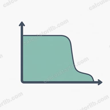
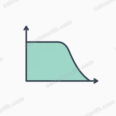
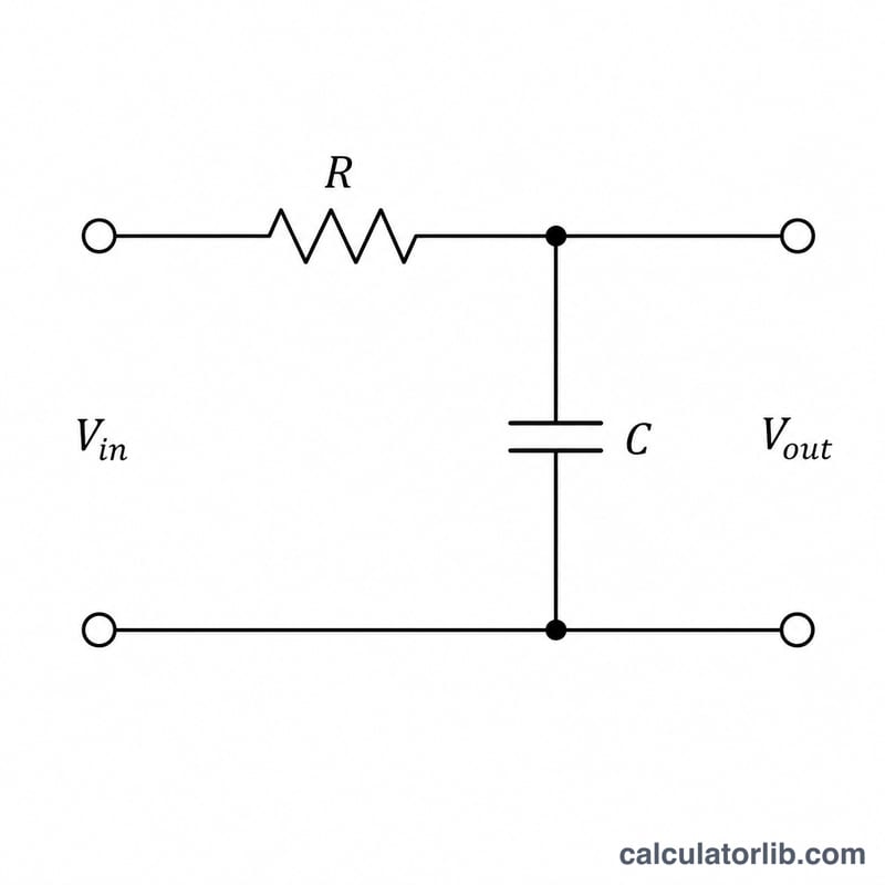
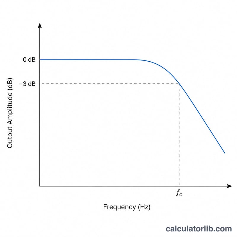
A low pass filter passes low-frequency signals while attenuating frequencies above its cutoff point. The most common type is the passive first-order RC filter, built from a single resistor and capacitor. This calculator finds the cutoff frequency (the −3 dB point) along with the time constant and angular frequency from the component values you enter.
How to use it
Enter the resistance R in ohms and the capacitance C in microfarads (µF). The calculator converts the capacitance to farads internally and returns the cutoff frequency in hertz. Use it to design audio crossovers, anti-aliasing filters, noise-reduction stages, or sensor signal conditioning.
The formula explained
The cutoff frequency is given by:
$$f_c = \frac{1}{2\pi \cdot \text{R }(\Omega) \cdot \text{C }(\mu F) \times 10^{-6}}$$At this frequency the filter's output power drops to half (−3 dB) of the input. Below \(f_c\) signals pass nearly unchanged; above it they roll off at 20 dB per decade. The time constant \(\tau = R \times C\) describes how fast the circuit charges, and the angular cutoff is \(\omega = 2\pi f_c\).
Worked example
With R = 1,000 \(\Omega\) and C = 0.1 µF (\(1 \times 10^{-7}\) F):
$$f_c = \frac{1}{2\pi \times 1000 \times 0.0000001} = \frac{1}{0.000628318} \approx 1591.55 \text{ Hz}$$The time constant \(\tau = 1000 \times 0.0000001 = 0.0001\ \text{s} = 0.1\ \text{ms}\).
Cutoff Frequency for Common R and C Combinations
For a first-order passive RC low pass filter, the cutoff (−3 dB) frequency is \(f_c = \frac{1}{2\pi R C}\) and the time constant is \(\tau = RC\). The table below applies these formulas to common component pairs.
| R | C | τ = RC (ms) | fc |
|---|---|---|---|
| 1 kΩ | 1 µF | 1.000 | 159.15 Hz |
| 1 kΩ | 0.1 µF | 0.100 | 1591.55 Hz (≈ 1.592 kHz) |
| 10 kΩ | 0.01 µF | 0.100 | 1591.55 Hz (≈ 1.592 kHz) |
| 100 Ω | 10 µF | 1.000 | 159.15 Hz |
| 10 kΩ | 0.1 µF | 1.000 | 159.15 Hz |
| 4.7 kΩ | 0.047 µF | 0.221 | 720.48 Hz |
Only the product RC matters: any pair with the same RC gives the same cutoff frequency. Doubling either R or C halves fc.
Example substitution for the last row: \(RC = 4700 \times 47\times10^{-9} = 2.209\times10^{-4}\) s, so \(f_c = \frac{1}{2\pi \times 2.209\times10^{-4}} \approx 720.48\) Hz.
Interpreting the Cutoff Frequency Result
The cutoff frequency fc is where the output amplitude falls to \(1/\sqrt{2} \approx 70.7\%\) of the input, which is −3.01 dB (half power). Below fc the filter passes signals nearly unchanged; above fc it attenuates them.
The gain magnitude of a first-order RC low pass filter is:
$$|H| = \frac{1}{\sqrt{1+\left(f/f_c\right)^2}}, \qquad \text{gain (dB)} = -10\log_{10}\left(1+(f/f_c)^2\right)$$
The phase shift is \(\varphi = -\arctan(f/f_c)\).
| Frequency | |H| | Gain (dB) | Phase |
|---|---|---|---|
| 0.1 fc | 0.995 | −0.04 dB | −5.71° |
| fc | 0.707 | −3.01 dB | −45° |
| 2 fc | 0.447 | −6.99 dB | −63.43° |
| 10 fc | 0.0995 | −20.04 dB | −84.29° |
- Roll-off: well above fc the response falls at 20 dB per decade (about 6 dB per octave) for this single-pole filter. For steeper roll-off, cascade stages or use an active or higher-order filter.
- Phase: the output lags the input by 45° at fc, approaching −90° as frequency increases.
- Step response: the 10%–90% rise time is about \(t_r \approx 2.2\,\tau = 2.2RC\), which is also \(t_r \approx 0.35/f_c\).
- Real-world impedances: the formula assumes an ideal voltage source and no load. A source resistance \(R_s\) adds to R in series, so use \(R_{total} = R + R_s\). A load resistance in parallel with C changes both the cutoff and the DC gain. As a rule of thumb, the load impedance should be at least 10 times R. Capacitor tolerance (often ±10% or ±20%) and resistor tolerance shift fc accordingly.
Unit Conversions for Resistance and Capacitance
The calculator takes resistance in ohms (Ω) and capacitance in microfarads (µF). Use these conversions to prepare your values.
| Capacitance | In farads (F) | In µF |
|---|---|---|
| 1 pF | 1×10⁻¹² F | 0.000001 µF |
| 1000 pF (1 nF) | 1×10⁻⁹ F | 0.001 µF |
| 1 nF | 1×10⁻⁹ F | 0.001 µF |
| 100 nF | 1×10⁻⁷ F | 0.1 µF |
| 1 µF | 1×10⁻⁶ F | 1 µF |
| Resistance | In ohms (Ω) |
|---|---|
| 1 kΩ | 1,000 Ω |
| 4.7 kΩ | 4,700 Ω |
| 1 MΩ | 1,000,000 Ω |
Frequency units
- 1 kHz = 1,000 Hz
- Angular frequency: \(\omega = 2\pi f\) (rad/s), so \(f = \omega / 2\pi\).
- The angular cutoff is \(\omega_c = \frac{1}{RC}\). For example, RC = 1 ms gives \(\omega_c = 1000\) rad/s, which equals \(1000/(2\pi) \approx 159.15\) Hz.
FAQ
What is the −3 dB point? It is the frequency where the output amplitude falls to about 70.7% of the input, marking the edge of the passband.
Does this work for an LC or active filter? No — this tool models a simple first-order passive RC filter. Other topologies use different equations.
Why microfarads? Most capacitors used in filters are in the nano- to microfarad range, so µF keeps the input convenient. The tool converts to farads before computing.