What is an RLC Circuit Calculator?
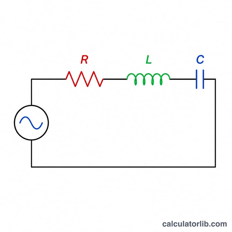
An RLC circuit combines a resistor (R), an inductor (L) and a capacitor (C). This calculator computes the key behaviour of a series RLC circuit: the resonant frequency, the angular resonant frequency, the quality factor (Q), and the bandwidth. These quantities describe how the circuit responds to signals of different frequencies and how sharply it is tuned.
How to use it
Enter the resistance in ohms, the inductance in henries, and the capacitance in farads. The calculator returns the resonant frequency in hertz, the angular frequency in radians per second, the dimensionless Q factor, and the bandwidth in hertz. Use SI units — for example, 1 mH is 0.001 H and 1 µF is 0.000001 F.
The formulas explained
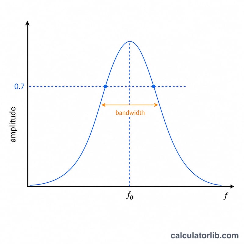
At resonance, the inductive reactance equals the capacitive reactance, giving a resonant frequency of \(f_0 = \frac{1}{2\pi\sqrt{\text{L}\cdot\text{C}}}\). The angular form is \(\omega_0 = \frac{1}{\sqrt{\text{L}\cdot\text{C}}}\). The quality factor for a series circuit is \(Q = \frac{1}{\text{R}}\sqrt{\frac{\text{L}}{\text{C}}}\); a higher Q means a narrower, more selective response. The bandwidth between the half-power points is \(\Delta f = \frac{f_0}{Q}\).
Worked example
Take R = 10 Ω, L = 1 mH (0.001 H), and C = 1 µF (0.000001 F). Then \(\sqrt{\text{LC}} = \sqrt{1\times10^{-9}} \approx 3.162\times10^{-5}\), so $$f_0 = \frac{1}{2\pi\cdot 3.162\times10^{-5}} \approx 5033 \text{ Hz}.$$ The Q factor is $$Q = \frac{1}{10}\cdot\sqrt{\frac{0.001}{0.000001}} = 0.1\cdot\sqrt{1000} \approx 3.162,$$ and the bandwidth is \(\frac{5033}{3.162} \approx 1592 \text{ Hz}\).
FAQ
Does this work for parallel RLC circuits? The resonant frequency formula is the same, but the Q factor for an ideal parallel circuit is \(Q = \text{R}\sqrt{\frac{\text{C}}{\text{L}}}\). This tool uses the series definition.
What does a high Q mean? A high Q indicates low energy loss relative to stored energy and a narrow bandwidth, making the circuit highly frequency-selective.
Why is my Q zero? If R is zero (ideal lossless), Q is undefined/infinite; this calculator returns 0 to avoid division by zero. Enter a small positive resistance for a realistic value.