
What Is True Position?
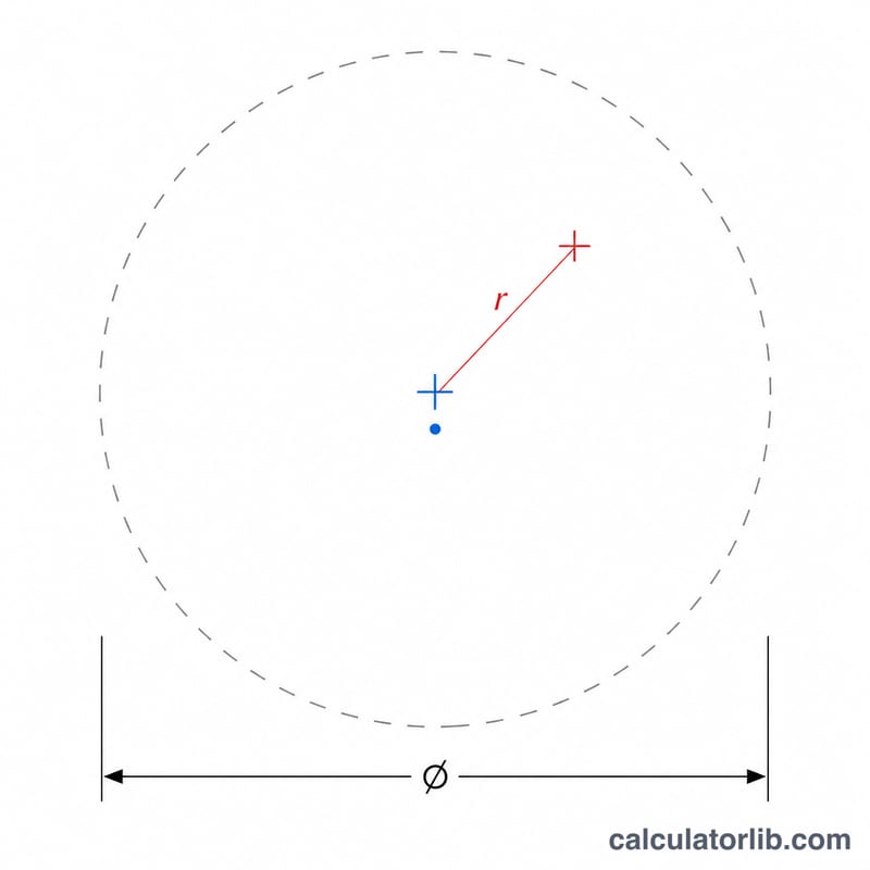
True position is a Geometric Dimensioning and Tolerancing (GD&T) control that defines how far a feature's actual center may deviate from its theoretically exact (nominal) location. Because the tolerance zone is a circle (in 2D) centered on the nominal point, true position is reported as a diameter — which is why the radial deviation is multiplied by two.
How to Use This Calculator
Enter the theoretically exact nominal X and Y coordinates of the feature, then enter the measured X and Y coordinates from your inspection (CMM, optical comparator, etc.). The calculator returns the true position value (the diameter of the tolerance zone needed to contain the feature) along with the X, Y, and radial deviations. Use consistent units throughout — millimeters or inches.
The Formula Explained
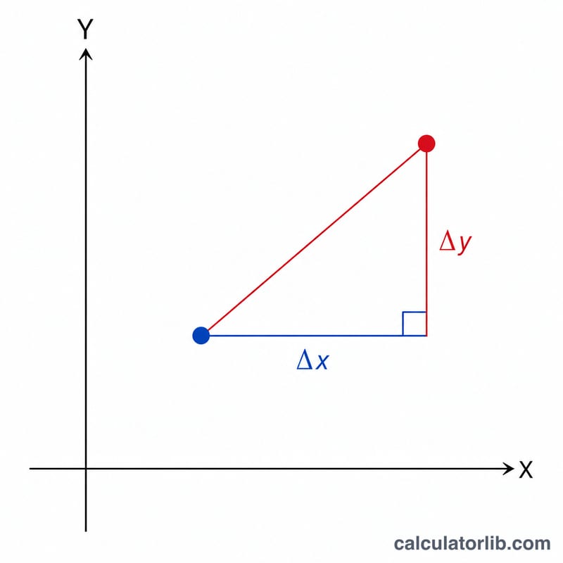
First find the deviations: \(\Delta x = \text{X}_{\text{measured}} - \text{X}_{\text{nominal}}\) and \(\Delta y = \text{Y}_{\text{measured}} - \text{Y}_{\text{nominal}}\). The radial deviation is \(r = \sqrt{(\Delta x)^2 + (\Delta y)^2}\), the actual distance from the true location. True position is $$\text{TP} = 2 \times r$$ because the cylindrical (circular) tolerance zone is specified by diameter, not radius.
Worked Example
A hole is nominally at (10, 10) mm and is measured at (10.3, 10.4) mm. \(\Delta x = 0.3\), \(\Delta y = 0.4\), so $$r = \sqrt{0.09 + 0.16} = \sqrt{0.25} = 0.5 \text{ mm}.$$ True position $$\text{TP} = 2 \times 0.5 = \mathbf{1.0 \text{ mm}}.$$ The feature is acceptable only if the drawing's positional tolerance is 1.0 mm or larger (before any bonus tolerance).
FAQ
Why multiply by 2? The positional tolerance zone is a circle/cylinder defined by its diameter. The measured point lies somewhere within that circle at radius \(r\), so the required diameter is \(2r\).
Does this include bonus tolerance? No. This computes the basic positional deviation. Bonus tolerance from MMC/LMC modifiers must be added to your allowed tolerance separately.
What units should I use? Any consistent unit. If nominal and measured are in millimeters, the result is in millimeters; if in inches, the result is in inches.