What this calculator does
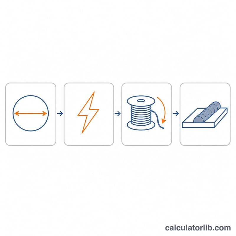
Every MIG weld is a balance: the wire has to leave the contact tip at exactly the speed the arc is melting it. Feed too slowly and the arc burns back and fuses the wire to the tip; feed too fast and the wire stubs into the plate with a machine-gun rattle. This tool turns your wire diameter, wire material and target welding current into a starting wire feed speed in inches per minute and metres per minute, plus deposition rate and a starting voltage.
The formula
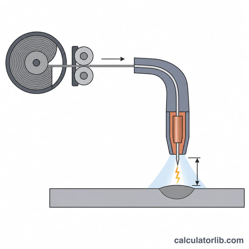
Melt-off is driven by volume, not by length, so a thicker wire runs slower at the same amperage. The feed speed is the melted volume per minute divided by the wire cross-section:
$$\text{WFS} = \frac{4 K_m I}{\pi d^2}$$where \(I\) = welding current in amps, \(d\) = wire diameter in inches, and \(K_m\) = the volumetric melt-off constant of the wire, about \(0.00154\) for mild steel, \(0.00160\) for stainless, \(0.00200\) for silicon bronze and \(0.00300\,\text{in}^3/\text{min}\) per amp for aluminium. Aluminium needs far less heat per unit volume, which is why an aluminium spool gun feeds two to three times faster than steel at the same amps.
These are starting numbers. Fine-tune by ear and by bead appearance: a harsh, spattery crackle usually means the wire feed speed is too high for the voltage, while a popping arc that burns back to the tip means it is too low.
Voltage is a rough starting point for short-circuit (steel, stainless, bronze) or spray/pulse (aluminum) transfer at a 3/8 in stickout. Always cross-check your machine door chart.
Worked example
Mild steel, 0.035 in wire, 150 A. The wire area is
$$A = \frac{\pi d^2}{4} = \frac{\pi \times 0.035^2}{4} = 0.000962\,\text{in}^2$$so the burn-off rate is \(0.00154 / 0.000962 = 1.60\) IPM per amp and
$$\text{WFS} = 1.60 \times 150 = 240\ \text{IPM} = 6.10\ \text{m/min}$$Deposition works out at \(0.00154 \times 150 \times 0.284 \times 60 \times 0.98 = 3.86\) lb/hr.
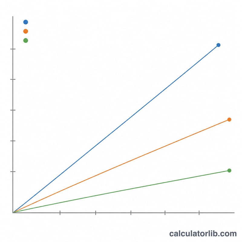
Wire Feed Speed & Amperage Settings by Wire Diameter
The table below gives shop starting points for solid ER70S-6 mild steel wire (AWS A5.18 classification, the US designation; the closest ISO 14341 equivalents are G3Si1/G4Si1). Wire feed speed (WFS) is calculated with the same melt-off relationship the calculator uses:
$$\text{WFS}_{\text{IPM}} = \frac{4 K_m \cdot A}{\pi d^{2}}, \qquad K_m = 0.00154\ \text{in}^3/\text{min per amp}$$
| Wire diameter | Usable amperage | WFS at low / high end (IPM) | WFS at low / high end (m/min) | Approx. arc voltage | Typical plate thickness |
|---|---|---|---|---|---|
| 0.023 in (0.6 mm) | 30–90 A | 111 / 334 | 2.8 / 8.5 | 14–18 V (short-circuit only) | 24 ga – 1/8 in (0.6–3 mm) |
| 0.030 in (0.8 mm) | 40–145 A | 87 / 316 | 2.2 / 8.0 | 15–20 V (short-circuit) | 22 ga – 3/16 in (0.8–5 mm) |
| 0.035 in (0.9 mm) | 50–200 A | 80 / 320 | 2.0 / 8.1 | 16–22 V short-circuit; ~24–28 V spray | 20 ga – 1/4 in (0.9–6 mm) |
| 0.045 in (1.2 mm) | 75–300 A | 73 / 290 | 1.8 / 7.4 | 17–23 V short-circuit; ~26–32 V spray | 1/8 – 1/2 in (3–12 mm), thicker in multipass |
Notice that every diameter lands in roughly the same 70–330 IPM feed-speed band at its own working current — drive rolls and liners are sized for that range, which is why a wire that is too large for the job simply will not feed slowly enough to run stably.
Note: these are starting points for short-circuit transfer with C25 (75% Ar / 25% CO₂) or 100% CO₂ shielding on clean material, DCEP, with roughly 3/8 in (10 mm) of contact-tip-to-work distance. Spray transfer requires an argon-rich mix (typically ≥ 80% Ar) and will not occur under 100% CO₂. Always confirm against the chart inside your machine's door and run a test bead on scrap of the same thickness — joint type, position, travel speed and gas mix all shift the final setting.
Melt-Off Constants and Wire Densities by Material
The melt-off constant \(K_m\) is the volume of wire the arc consumes per minute per amp of welding current. Divide that volume by the wire's cross-sectional area \(\pi d^{2}/4\) and you get the burn-off rate in inches of wire per minute per amp — multiply it by your amperage and you have the feed speed.
| Wire type (AWS class) | \(K_m\) (in³/min per amp) | Density \(\rho\) (lb/in³) | Burn-off 0.030 in (IPM/A) | Burn-off 0.035 in (IPM/A) | Burn-off 0.045 in (IPM/A) |
|---|---|---|---|---|---|
| Mild steel — ER70S-6 (ER70S-3 similar) | 0.00154 | 0.284 | 2.18 | 1.60 | 0.97 |
| Stainless — ER308L / ER316L | 0.00160 | 0.286 | 2.26 | 1.66 | 1.01 |
| Aluminium — ER4043 / ER5356 | 0.00300 | 0.098 | 4.24 | 3.12 | 1.89 |
| Silicon bronze — ERCuSi-A | 0.00200 | ~0.313 | 2.83 | 2.08 | 1.26 |
| Metal-cored / flux-cored (E70C-6M, E71T-1) | Not a single solid-wire constant — see note | Effective density below solid steel (tubular) | Use the manufacturer's WFS/amperage chart | ||
How to read the burn-off columns: 0.035 in steel burns off at about 1.60 IPM per amp, so 150 A ≈ 240 IPM. The same 0.035 in wire in ER4043 aluminium burns off at 3.12 IPM per amp because aluminium's low melting point and high thermal conductivity consume far more wire volume per amp — hence roughly double the feed speed at identical current.
Deposition efficiency: the calculator assumes ~0.98 (98%) for solid wire under gas shielding — spatter and a small amount of vaporisation account for the loss, and there is no slag. Gas-shielded flux-cored wire is typically nearer 0.80–0.90 and self-shielded flux-cored lower still, because part of the fill becomes slag rather than weld metal; metal-cored wire sits close to solid wire. Deposition rate therefore always trails melt-off rate:
$$\text{Deposition}_{\text{lb/hr}} = K_m \cdot A \cdot \rho \cdot 60 \cdot \eta$$
Note that \(K_m\) and \(\rho\) here are expressed in US customary units (in³/min per amp and lb/in³), which is how North American filler-metal data is normally published; the calculator converts the output to m/min and you can convert lb/hr to kg/h by multiplying by 0.4536.
Key MIG Welding Terms Explained
- Wire feed speed (WFS)
- How fast the drive rolls push filler wire out of the gun, measured in inches per minute (IPM) in North America or metres per minute (m/min) elsewhere. \(1\ \text{m/min} = 39.37\ \text{IPM}\); the calculator reports both.
- Burn-off rate
- Inches of wire the arc melts per minute for each amp of current, \(4K_m/(\pi d^{2})\). It is fixed by wire diameter and alloy, and it is what links amperage to feed speed.
- Melt-off constant \(K_m\)
- The volume of wire melted per minute per amp (in³/min·A). It is material-specific — 0.00154 for mild steel, 0.00300 for aluminium — and folds in the alloy's melting point, heat capacity and arc behaviour.
- Deposition rate
- The weight of metal actually left in the joint per hour (lb/hr or kg/h). It is always lower than the melt-off rate because spatter and vaporisation — and slag, with flux-cored wire — remove part of what melted. The calculator applies a 0.98 efficiency for solid wire.
- Contact tip to work distance (CTWD) / stickout
- The distance from the end of the contact tip to the workpiece. Longer CTWD adds resistive preheating of the electrode extension, so on a constant-voltage machine the wire melts off at a lower current — the amperage drops even though nothing on the dial changed. Around 3/8 in (10 mm) is a normal short-circuit reference.
- Arc voltage
- The voltage measured across the arc. It controls arc length and bead shape: too low gives a ropey, stubbing bead, too high gives a wide, flat bead with undercut and spatter.
- CV (constant voltage) power source
- The standard MIG machine type. It holds voltage nearly constant and lets current self-adjust to keep arc length stable. This is why feed speed effectively sets the amperage: feeding faster forces the arc to draw more current to melt the wire. The amps you enter in this calculator are therefore the target current you expect to draw, and the tool tells you the feed speed that will produce it.
- Short-circuit transfer
- Low current and voltage; the wire repeatedly touches the puddle and the short clears in a small spatter event. Low heat input — best for sheet, thin wall and out-of-position work, and the only mode available with 100% CO₂.
- Globular transfer
- The transitional range above short-circuit: large irregular droplets fall across the arc. Spattery and generally avoided.
- Spray transfer
- High current with an argon-rich shielding gas (typically ≥ 80% Ar); metal crosses as a fine stream of droplets. Smooth, fast and high-deposition, but the fluid puddle limits it mostly to flat and horizontal fillet positions on thicker material.
- Duty cycle
- The share of a ten-minute period a machine can weld at a given output without overheating — e.g. 60% at 200 A means six minutes welding, four minutes cooling. Ratings are usually declared to IEC 60974-1 (or NEMA EW-1 on older US equipment), so compare like with like.
- Drive roll and tension
- The grooved rollers that push the wire. Use V-groove for solid steel, knurled V for flux-cored, and U-groove for soft aluminium. Set tension just above the point where the wire stops slipping against light resistance — over-tightening deforms the wire and causes birdnesting.
All of these figures are starting points for setup and estimating. Confirm settings on scrap, and follow the welding procedure specification and safety requirements that apply to your work.
FAQ
How do I pick the amperage? A common shop rule for mild steel is about 1 amp per 0.001 in of plate thickness, so 1/8 in steel starts near 125 A. Thicker sections with a bevel can take more.
My machine only has a numbered knob. Many hobby welders label feed 1-10 rather than IPM. Use the calculated IPM to find the matching speed on the machine door chart, or measure: run the wire for 6 seconds with the gun trigger pulled and no gas, then multiply the length fed by 10.
Does stickout change the answer? Yes. Longer electrode stickout adds resistive preheating, so the same feed speed draws fewer amps. These figures assume a normal 3/8 in stickout; if you extend it, expect to nudge the feed speed up slightly.