What Is a Taper?
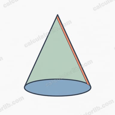
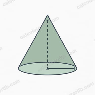
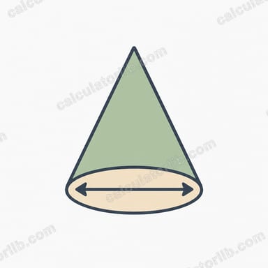
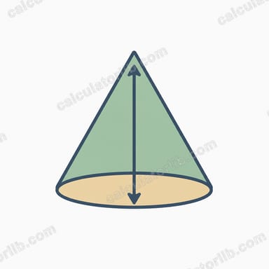
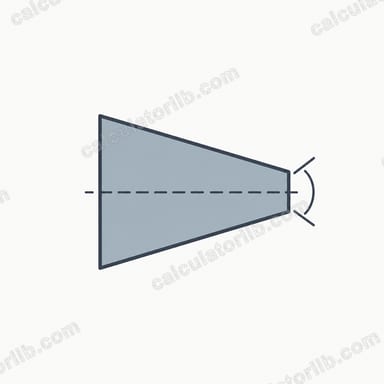
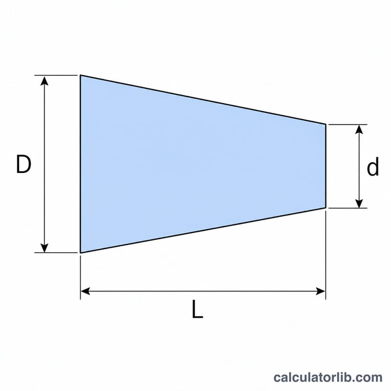
A taper is a gradual reduction in diameter along the length of a part, common in shafts, pins, tool holders, and reamers. This calculator finds the taper per unit length, the taper percent, and the taper angle from a large diameter (D), a small diameter (d), and the axial length (L) over which the change occurs. It is unit-agnostic: enter all three measurements in the same units (mm or inches) and the taper ratio and angles stay valid.
How to Use It
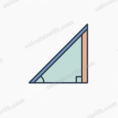
Enter the large diameter, the small diameter, and the length between those two measured points. The calculator returns the taper per unit length (rise over run on the diameter), the taper expressed as a percent, the full included angle between the opposing surfaces, and the half angle measured from the centerline to one side — the value most machinists set on a compound rest or sine bar.
The Formula Explained
Taper per unit length is simply the diameter difference divided by the length: \( T = (D - d) / L \). Because the diameter changes on both sides of the axis, each side rises by half that amount. The half angle is therefore \( \arctan((D - d) / (2L)) \), and the full included angle is twice that. Taper percent is the per-unit taper multiplied by 100.
$$\text{Taper} = \frac{\text{Large Dia. }(D) - \text{Small Dia. }(d)}{\text{Length }(L)}$$$$\theta = 2\,\arctan\!\left(\frac{\text{Large Dia. }(D) - \text{Small Dia. }(d)}{2\,\text{Length }(L)}\right)$$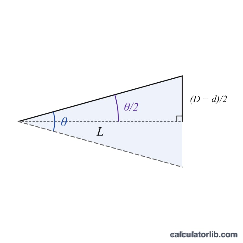
Worked Example
For \( D = 2 \), \( d = 1 \), \( L = 10 \): taper per unit =
$$(2 - 1) / 10 = 0.1$$or 10%. The half angle =
$$\arctan(1 / 20) = \arctan(0.05) \approx 2.8624^\circ$$so the included angle \( \approx 5.7249^\circ \).
Standard Machine Tapers Reference
Most self-holding and self-releasing machine tapers are defined by a taper per foot (TPF) in inches — a US/inch convention documented in ASME B5.10 (machine tapers) and mirrored internationally by ISO 296 / DIN 228 for Morse and metric tapers. The angles below are computed from the nominal taper per foot using \(\text{half angle} = \arctan\!\left(\frac{T}{2}\right)\), where \(T\) is taper per inch. They are reference values for identification and layout work — for tool or spindle manufacture, always verify against the current edition of ASME B5.10 / ISO 296 or the maker's print, since gauge diameters, socket lengths and tolerances (not just the angle) define the fit.
| Taper | Taper per foot (in/ft) | Taper per inch | Half angle | Included angle | Type |
|---|---|---|---|---|---|
| Morse No. 0 | 0.62460 | 0.052050 | 1.4908° | 2.9816° | Self-holding |
| Morse No. 1 | 0.59858 | 0.049882 | 1.4286° | 2.8572° | Self-holding |
| Morse No. 2 | 0.59941 | 0.049951 | 1.4306° | 2.8612° | Self-holding |
| Morse No. 3 | 0.60235 | 0.050196 | 1.4376° | 2.8752° | Self-holding |
| Morse No. 4 | 0.62326 | 0.051938 | 1.4876° | 2.9752° | Self-holding |
| Morse No. 5 | 0.63151 | 0.052626 | 1.5073° | 3.0146° | Self-holding |
| Brown & Sharpe (nominal) | 0.502 | 0.041833 | 1.1981° | 2.3961° | Self-holding |
| Jarno (all sizes) | 0.600 | 0.050000 | 1.4319° | 2.8638° | Self-holding |
| NMTB / CAT / ISO 7:24 (V-flange) | 3.500 | 0.291667 | 8.2971° | 16.5943° | Self-releasing |
| Jacobs No. 0 | 0.59145 | 0.049288 | 1.4116° | 2.8232° | Self-holding |
| Jacobs No. 1 | 0.92508 | 0.077090 | 2.2075° | 4.4150° | Self-holding |
| Jacobs No. 2 | 0.97861 | 0.081551 | 2.3349° | 4.6697° | Self-holding |
| Jacobs No. 33 | 0.76194 | 0.063495 | 1.8182° | 3.6364° | Self-holding |
| Jacobs No. 6 | 0.62661 | 0.052218 | 1.4956° | 2.9912° | Self-holding |
Notes. Morse tapers are not a single angle: the nominal taper per foot varies by number from about 0.5986 to 0.6315 in/ft, so an MT2 arbor is not geometrically identical to an MT5 scaled up. The widely quoted "about 5/8 in per foot, roughly 1.5° per side" is a useful approximation only. The Bridgeport-style R8 spindle nose is a short, much steeper taper commonly cited near 16.85° included (≈8.43° per side) with a 0.9495 in nominal large diameter; because published R8 figures differ in whether they state the per-side or included angle, confirm it against the spindle or collet manufacturer's drawing before cutting one.
Self-holding vs self-releasing. Self-holding (slow) tapers such as Morse, Brown & Sharpe, Jarno and Jacobs have half angles of roughly 1°–2.5°, below the friction angle of steel on steel, so the shank grips and transmits torque by friction and must be knocked out with a drift. Self-releasing (steep or "fast") tapers such as the 7:24 NMTB/CAT/ISO family have a 8.3° half angle, well above the friction angle: they centre the toolholder but will not stick, so torque is carried by drive keys or flange dogs and the holder is held in by a drawbar or retention knob.
Taper Unit Conversion Table
Taper is a pure ratio — a change in diameter per unit of axial length — so the same geometry can be written five different ways. Let \(T\) be the taper per unit length (taper per inch when working in inches, mm per mm in metric):
$$T = \frac{D - d}{L}, \qquad \text{TPF} = T \times 12, \qquad T = \frac{1}{N} \text{ for a ratio } 1:N$$
$$\text{Taper \%} = T \times 100, \qquad \alpha_{1/2} = \arctan\!\left(\frac{T}{2}\right), \qquad \alpha_{\text{incl}} = 2\,\alpha_{1/2}$$
Decimal degrees convert to minutes with \(\text{minutes} = (\text{decimal part}) \times 60\), and to seconds with a further \(\times 60\). The division by 2 inside the arctangent is essential: the taper is a diametral change, but the angle of the surface to the axis is set by the radial rise, which is half of it. Note that taper per foot is meaningful only for inch work; for metric parts, quote the ratio, the percent, or the angle instead.
| Ratio 1:N | Taper per unit length \(T\) | Taper per foot (in/ft) | Taper percent | Half angle (decimal) | Half angle (deg–min–sec) | Included angle |
|---|---|---|---|---|---|---|
| 1:20 | 0.050000 | 0.6000 | 5.0000% | 1.4319° | 1°25′55″ | 2.8638° |
| 1:16 | 0.062500 | 0.7500 | 6.2500% | 1.7899° | 1°47′24″ | 3.5798° |
| 1:10 | 0.100000 | 1.2000 | 10.0000% | 2.8624° | 2°51′45″ | 5.7248° |
| 1:19.2000 | 0.052083 | 0.6250 | 5.2083% | 1.4918° | 1°29′30″ | 2.9835° |
| 1:23.9044 | 0.041833 | 0.5020 | 4.1833% | 1.1981° | 1°11′53″ | 2.3961° |
| 1:3.4286 | 0.291667 | 3.5000 | 29.1667% | 8.2971° | 8°17′50″ | 16.5943° |
Reading the table both ways: a print calling for "taper 1:20" and a print calling for "0.600 in per foot" describe the same cone, and the 7:24 spindle taper (3.500 in/ft) is simply \(7/24 = 0.291667\) expressed per inch. Because the arctangent is non-linear, angles cannot be scaled the way ratios can — doubling the taper does not exactly double the angle, though at small tapers the error is tiny.
Taper Results Across Common Scenarios
Every row below is computed from the same three inputs using \(T = \frac{D - d}{L}\) and \(\alpha_{1/2} = \arctan\!\left(\frac{D - d}{2L}\right)\). Ratios and angles are rounded to four decimals. Because taper per unit length is dimensionless, the "taper per foot" column is still computable for the metric rows (\(T \times 12\)) as an inch-equivalent, but it would not normally be quoted on a metric drawing.
| Case | D | d | L | Taper per unit | Taper percent | Taper per foot | Half angle | Included angle | Ratio |
|---|---|---|---|---|---|---|---|---|---|
| Metric shaft | 25 mm | 20 mm | 100 mm | 0.0500 | 5.0000% | 0.6000 | 1.4319° | 2.8638° | 1:20.0000 |
| Short metric cone | 50 mm | 45 mm | 50 mm | 0.1000 | 10.0000% | 1.2000 | 2.8624° | 5.7248° | 1:10.0000 |
| Inch plug (1:16) | 1.000 in | 0.875 in | 2.000 in | 0.0625 | 6.2500% | 0.7500 | 1.7899° | 3.5798° | 1:16.0000 |
| Near-Morse shank | 0.700 in | 0.572 in | 2.500 in | 0.0512 | 5.1200% | 0.6144 | 1.4665° | 2.9329° | 1:19.5313 |
| NMTB-like steep taper | 1.750 in | 1.250 in | 1.714 in | 0.2917 | 29.1715% | 3.5006 | 8.2985° | 16.5970° | 1:3.4280 |
Reading the comparison. The first two rows have the same 5 mm diameter difference, but halving the length doubles the taper and roughly doubles the angle — taper depends on the difference and the length, never on the diameters alone. The 1:16 inch plug and the 1:20 metric shaft sit in the self-holding range; the near-Morse row at 0.6144 in/ft lands between the nominal Morse No. 3 and No. 4 values from the reference table, close enough that only gauge-diameter and length checks would identify the actual size. The final row reproduces the 7:24 self-releasing spindle taper to within a few ten-thousandths of a degree, which shows how sensitive a steep taper is: changing \(L\) by 0.001 in there shifts the angle more than a 0.001 in change would on any of the slow tapers.
FAQ
What units should I use? Any, as long as all three inputs share the same unit. Taper per unit and angles are dimensionless ratios.
What is the difference between included and half angle? The included angle spans both sides of the part; the half angle is from the centerline to one face — used when offsetting a compound slide.
How do I convert to taper per foot? Multiply the taper per unit (in inches per inch) by 12 to get inches per foot.