What this calculator does
The Welding Amperage Calculator gives a quick, sensible starting current for MIG or stick (SMAW) welding based on two things you already know: how thick the metal is and which electrode or wire diameter you are running. Set your machine near this value, lay a test bead, and fine-tune from there. It is built for mild steel and works as a rule-of-thumb rather than a code-qualified procedure.
How to use it
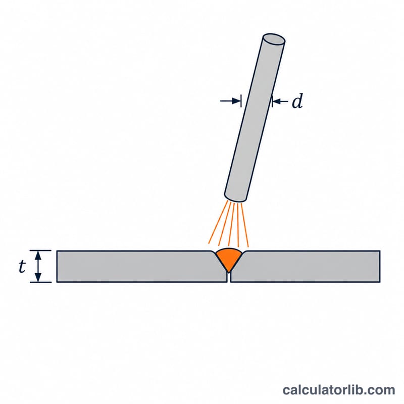
Enter the material thickness in millimetres and the diameter of your stick electrode or MIG wire in millimetres, then read the recommended amperage and the suggested working range. Thicker metal needs more heat to fuse, and a larger electrode carries more current, so both inputs push the number up.
The formula explained
Both the classic thickness guideline and the electrode guideline for mild steel land close to \(40\ \text{A}\) per millimetre. Averaging them gives a single value that respects each input equally:
$$A = 20 \times (t + d)$$
where \(A\) = recommended amperage in amps, \(t\) = material thickness in mm, and \(d\) = electrode or wire diameter in mm. The suggested range is simply \(0.9A\) to \(1.1A\), a practical window for dialing in penetration.
Worked example
Welding \(3\,\text{mm}\) plate with a \(2.4\,\text{mm}\) electrode:
$$A = 20 \times (3 + 2.4) = 20 \times 5.4 = 108\ \text{A}$$
That puts the working range at roughly \(97\) to \(119\ \text{A}\). Start around 108 A, watch the bead, and adjust for travel speed and position.
Typical Amperage by Thickness and Electrode Size (Mild Steel)
The tables below show general, manufacturer-style guideline ranges for mild (low-carbon) steel in the flat position. They are rules of thumb, not code-qualified welding procedure specifications (WPS). They may differ somewhat from the calculator's output, because the calculator uses one simple linear formula, \(I = 20 \times (t + d)\), for every process. A "—" means the combination is not normally practical.
Stick (SMAW), E6013 / E7018, amps
| Plate thickness | 2.5 mm rod | 3.2 mm rod | 4.0 mm rod | 5.0 mm rod |
|---|---|---|---|---|
| 1.5 mm | 50–70 | — | — | — |
| 2 mm | 60–80 | — | — | — |
| 3 mm | 70–95 | 90–120 | — | — |
| 4 mm | — | 100–130 | 120–150 | — |
| 5 mm | — | 110–140 | 130–170 | — |
| 6 mm | — | 110–140 | 140–180 | 180–220 |
| 10 mm (multipass) | — | 100–140 (root) | 150–190 | 190–240 |
MIG/MAG solid wire (short-circuit transfer, Ar/CO₂ or CO₂), amps
| Plate thickness | 0.6 mm wire | 0.8 mm wire | 0.9 mm wire | 1.2 mm wire |
|---|---|---|---|---|
| 1.5 mm | 40–70 | 50–100 | 60–110 | — |
| 2 mm | 50–80 | 70–120 | 80–130 | 100–140 |
| 3 mm | — | 90–140 | 100–160 | 120–180 |
| 4 mm | — | 110–150 | 120–180 | 140–200 |
| 5 mm | — | — | 150–200 | 160–220 |
| 6 mm | — | — | 170–220 | 180–250 |
| 10 mm (multipass) | — | — | — | 200–280 |
Actual settings depend on joint design, shielding gas, wire type, power source and travel speed. Always confirm against the consumable maker's datasheet.
Scenario Comparison: Recommended Amps for Common Jobs
Each row applies \(I = 20 \times (t + d)\) with a working range of \(0.9I\) to \(1.1I\).
| Job | Substitution | Recommended I (A) | Range (A) |
|---|---|---|---|
| 1.5 mm sheet, 0.8 mm MIG wire | \(20 \times (1.5 + 0.8)\) | 46 | 41.4–50.6 |
| 2 mm plate, 2.5 mm rod | \(20 \times (2 + 2.5)\) | 90 | 81–99 |
| 3 mm plate, 2.4 mm rod | \(20 \times (3 + 2.4)\) | 108 | 97.2–118.8 |
| 6 mm plate, 3.2 mm rod | \(20 \times (6 + 3.2)\) | 184 | 165.6–202.4 |
| 10 mm plate, 4.0 mm rod | \(20 \times (10 + 4.0)\) | 280 | 252–308 |
Where results fall outside practical limits:
- The 10 mm / 4.0 mm case gives 280 A, well above what a 4.0 mm stick electrode can carry (typically about 130–200 A). Use a larger electrode, or weld thick plate in several passes at the electrode's own rated current.
- The 6 mm / 3.2 mm case (184 A) is above the usual 3.2 mm stick range of roughly 90–140 A. Treat it as an upper bound and expect to use multiple passes or a 4.0 mm rod.
- The 1.5 mm / 0.8 mm case (46 A) is low for a MIG machine on some settings. It may fall below the stable arc range of your welder.
The formula takes no account of process, position or wire type. Whenever the result falls outside the consumable's rated range, the rated range wins.
Interpreting Your Amperage Result
The calculator gives one recommended current \(I\) plus a range from \(0.9I\) to \(1.1I\). Start near the middle of the range, make a test bead on scrap of the same material, and adjust in small steps.
Signs the current is too low
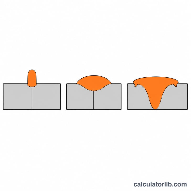
- Poor fusion or cold lap: the bead sits on top of the plate instead of wetting into it.
- A narrow, ropey, high-crowned bead.
- Electrode sticking or a difficult, unstable arc start.
- Shallow penetration and a risk of incomplete fusion at the root.
Signs the current is too high
- Excess spatter and an overly fluid, flat, wide puddle.
- Undercut along the bead toes.
- Burn-through or distortion on thin sheet.
- A rod that glows red or overheats, damaging its coating.
Factors that shift the setting
- Position: vertical and overhead welding usually need lower current (often about 10–20% less) so the puddle stays controllable.
- Joint type: a butt joint with a gap, a fillet or a lap joint each carries heat differently. Thick sections and T-joints conduct heat away and may need more current than a thin lap joint.
- Material: the formula is a mild-steel rule of thumb. Stainless, aluminum and high-strength steels need different settings and often different processes.
Relationship to the electrode's rated range
Every electrode or wire has a recommended current range printed on its packaging or datasheet. If the calculated value (or its \(0.9I\)–\(1.1I\) range) lies outside that range, stay within the rated range and choose a different diameter or use multiple passes instead.
Note: this result is a starting baseline, not a qualified procedure. The electrode or wire manufacturer's datasheet, and any applicable welding procedure specification, take precedence.
FAQ
Does this work for aluminium or stainless? It is tuned for mild steel. Aluminium usually needs more current and stainless a little less, so treat the result as a baseline.
Should the electrode be thicker than the metal? Generally no. Match electrode diameter to thickness or go slightly smaller on thin sheet to avoid burn-through.
Why a range instead of one number? Position, joint fit-up, and travel speed all shift the ideal current, so a range lets you tune to the actual weld.