What Is the CNC Milling Time Calculator?
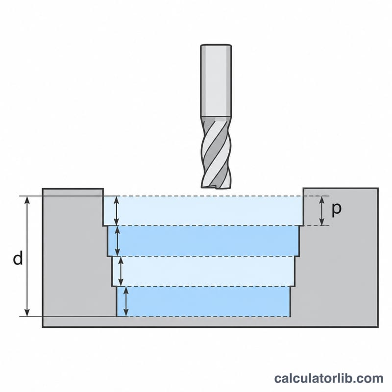
The CNC Milling Time Calculator estimates how long a milling operation will take from four practical inputs: the total toolpath length, the programmed feed rate, the total depth of cut, and the depth removed per pass. It gives machinists, CAM programmers, and shop planners a fast way to predict cycle time before cutting metal, which helps with quoting, scheduling, and tool-life planning.
The Formula Explained
Milling time depends on how far the cutter travels and how quickly it moves. First, the number of passes \(N\) is the total depth divided by the depth per pass, rounded up:
$$N = \left\lceil \frac{D}{a_p} \right\rceil$$where \(D\) = total depth of cut and \(a_p\) = depth of cut per pass. The total cutting distance is the toolpath length \(L\) multiplied by \(N\), and the machining time \(T\) is that distance divided by the feed rate \(F\):
$$T = \frac{L \times N}{F}$$Here \(L\) = toolpath length in mm, \(F\) = feed rate in mm/min, and \(T\) is in minutes.
How to Use It
Enter the toolpath length your CAM software reports, the feed rate from your cutting parameters, and both depth values. The calculator returns the number of passes, the total cutting distance, and the estimated machining time. Because feed rate dominates the result, make sure it matches your actual program feed rather than the machine rapid rate.
Worked Example
Suppose \(L = 500\) mm, \(F = 200\) mm/min, \(D = 10\) mm, and \(a_p = 2\) mm. The number of passes is
$$N = \left\lceil \frac{10}{2} \right\rceil = 5$$The total distance is \(500 \times 5 = 2500\) mm, so the machining time is
$$T = \frac{2500}{200} = 12.5\ \text{min}$$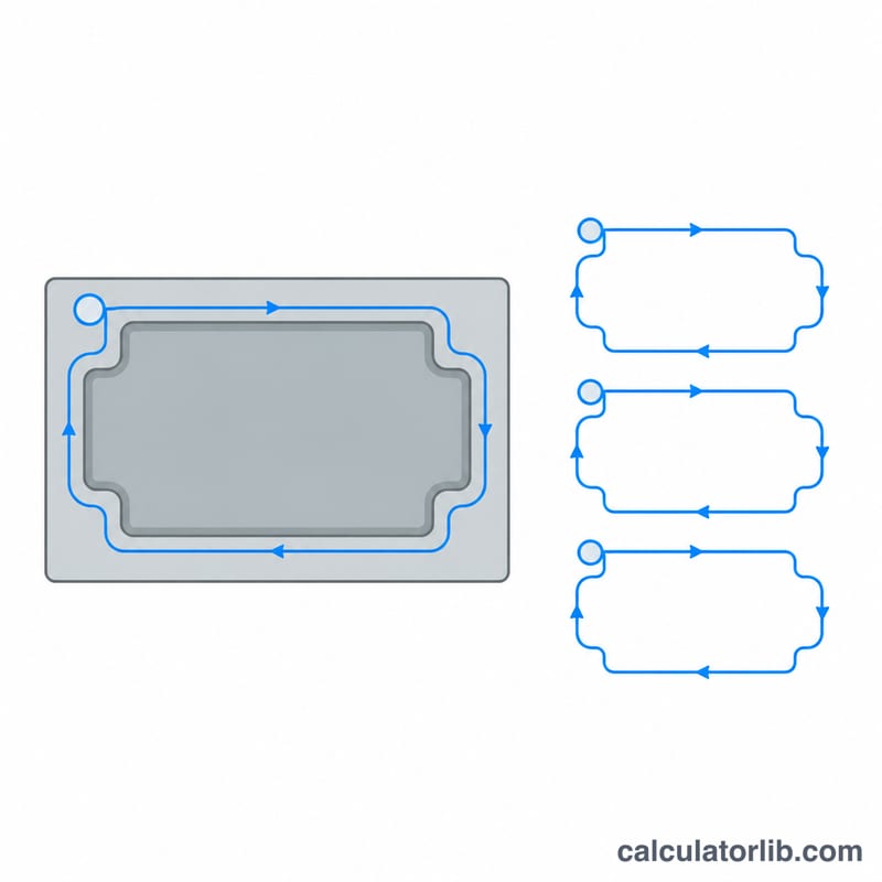
More Worked Examples
Each example uses the same three steps. First, find the number of passes \(N\) by rounding \(D / a_p\) up to the next whole number. Next, multiply the number of passes by the toolpath length to get the total cutting distance. Then divide that distance by the feed rate to get the time. The formula works in any consistent unit system. If length is in millimetres and feed is in mm/min, or length is in inches and feed is in in/min, the result is in minutes.
Example 1: Metric pocket, 7 mm deep
Inputs: total depth \(D = 7\) mm, depth per pass \(a_p = 2\) mm, toolpath length per pass \(L = 800\) mm, feed rate \(F = 300\) mm/min.
- Number of passes: $$N = \left\lceil \frac{7}{2} \right\rceil = \lceil 3.5 \rceil = 4$$ A cutter can't take half a pass, so 3.5 rounds up to 4. Three full 2 mm passes remove 6 mm, and a fourth, lighter pass removes the last 1 mm.
- Total cutting distance: $$L \times N = 800 \times 4 = 3200\ \text{mm}$$
- Cutting time: $$T = \frac{3200}{300} = 10.6667\ \text{min}$$
- Convert to minutes and seconds: $$0.6667 \times 60 = 40\ \text{s}$$ The result is 10.67 min, or about 10 min 40 s.
Example 2: Inch units, 0.5 in deep
Inputs: \(L = 24\) in, \(F = 15\) in/min, \(D = 0.5\) in, \(a_p = 0.125\) in.
- Number of passes: $$N = \left\lceil \frac{0.5}{0.125} \right\rceil = \lceil 4 \rceil = 4$$ The depth divides evenly, so no rounding is needed.
- Total cutting distance: $$L \times N = 24 \times 4 = 96\ \text{in}$$
- Cutting time: $$T = \frac{96}{15} = 6.4\ \text{min}$$
- Convert to minutes and seconds: $$0.4 \times 60 = 24\ \text{s}$$ The result is 6.4 min, or 6 min 24 s.
Don't mix unit systems. If the length is in inches, the feed must be in inches per minute.
How Depth per Pass and Feed Rate Change Machining Time
In the table below, the toolpath length is fixed at \(L = 500\) mm and the total depth at \(D = 10\) mm. Only the depth per pass \(a_p\) and the feed rate \(F\) change. Each row uses \(N = \lceil D / a_p \rceil\), distance \(= L \times N\) and \(T = \text{distance} / F\).
| Depth per pass ap (mm) | Passes N | Total cutting distance (mm) | T at F = 100 mm/min (min) | T at F = 200 mm/min (min) | T at F = 400 mm/min (min) |
|---|---|---|---|---|---|
| 1 | 10 | 5000 | 50 | 25 | 12.5 |
| 2 | 5 | 2500 | 25 | 12.5 | 6.25 |
| 2.5 | 4 | 2000 | 20 | 10 | 5 |
| 4 | 3 | 1500 | 15 | 7.5 | 3.75 |
| 5 | 2 | 1000 | 10 | 5 | 2.5 |
What the table shows:
- Doubling the feed rate halves the cutting time, because \(T\) is inversely proportional to \(F\).
- Because the pass count rounds up, time changes in steps. At \(a_p = 4\) mm, \(10/4 = 2.5\) rounds up to 3 passes, and the third pass removes only 2 mm. Raising \(a_p\) from 4 mm to 5 mm saves a whole pass. Choosing a depth per pass that divides the total depth evenly avoids a lightly loaded final pass.
- The fastest case here (5 mm depth per pass at 400 mm/min, 2.5 min) is 20 times faster than the slowest (1 mm at 100 mm/min, 50 min).
Note: These numbers only show the arithmetic. They don't recommend any cutting parameters. Deeper passes and higher feeds raise cutting forces, spindle load and tool deflection. The depth per pass and feed rate you choose must stay within the tool manufacturer's recommendations, your machine's power and rigidity, and what your workholding can hold. A shorter estimate is worthless if the tool breaks or the part comes out of tolerance.
Turning the Estimate into a Realistic Cycle Time
The calculator gives the time the tool spends cutting at the programmed feed. A real cycle time on the machine also includes movements and stops that aren't cutting. To get a planning figure you can rely on:
- Use the actual programmed cutting feed. Enter the feed rate that is in the program for the cutting moves. Don't use the machine's rapid traverse rate, which applies only to non-cutting positioning moves.
- Run the calculation once per operation. Roughing and finishing usually use different depths per pass, feeds and toolpath lengths. Calculate each operation on its own, then add the results. For example, if roughing takes 12.5 min and a finishing pass takes 3 min, total cutting time is 15.5 min.
- Add time for non-cutting moves. Include rapids between features, approach and retract moves, plunges or ramps, and lead-in and lead-out moves. CAM software or a dry run on the controller can give you these times.
- Add tool changes and setup. Count each tool change. Also add part loading, fixturing, probing or zero-setting, and inspection if they fall inside the cycle you are quoting or scheduling.
- Expect the real cut to take longer than the estimate. If the operator turns the feed override below 100%, every cutting move slows down. The machine also has to slow down and speed up in corners, short segments and tight arcs. On detailed toolpaths the average feed can be well below the programmed value.
- Add a contingency only if your shop wants one. Some shops add an allowance on top of the summed time. There is no universal standard for this. Base the size of any allowance on your own machines, materials and past job records. Then compare your estimates with actual cycle times and adjust.
Use the result as a lower bound for cutting time. It is best for comparing toolpath strategies and pass depths. Measured times from the machine should replace it once a part is in production.
FAQ
Does this include rapid moves or tool changes? No. It estimates cutting time along the programmed feed path. Add allowances for rapids, approach moves, and tool changes to get a full cycle time.
Can I use inches? Yes, as long as length and feed rate use the same unit system (for example inches and inches per minute); the time unit follows your inputs.
Why are passes rounded up? A partial pass still requires a full cutting stroke, so the pass count is always rounded up to the next whole number.