What is the CNC Turning Time Calculator?
This calculator estimates how long a lathe needs to turn a cylindrical feature. It combines the geometry of the part (starting and final diameter, length of cut) with your cutting parameters (spindle speed, feed per revolution and depth of cut) to give cutting time, total cycle time and batch time. It uses metric units: millimetres, mm/rev and RPM.
How to use it
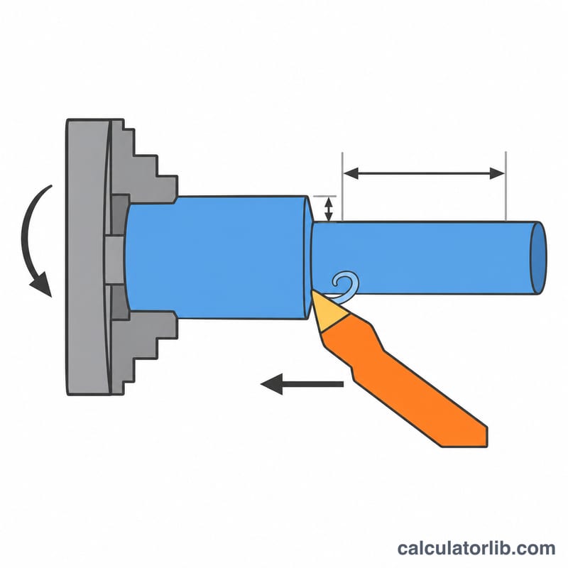
Enter the bar diameter and the finished diameter, the length to be turned, and the extra approach and overrun distance per pass. Then enter the spindle speed in RPM, the feed per revolution and the maximum radial depth of cut per pass. Add any non-cutting time per part (loading, tool changes, rapid moves) in seconds and the number of parts in the batch.
The formula explained
The feed rate is spindle speed times feed per revolution: \(F = n \times f\) in mm/min. The number of passes is the radial stock divided by the depth of cut, rounded up:
$$N_p = \left\lceil \frac{(D_0 - D_1)/2}{a_p} \right\rceil$$Cutting time is then:
$$T_c = \frac{N_p \times (L + A)}{n \times f}$$Here \(D_0\) = starting diameter, \(D_1\) = final diameter, \(a_p\) = depth of cut, \(L\) = length of cut, \(A\) = approach plus overrun, \(n\) = RPM and \(f\) = feed per revolution.
Worked example
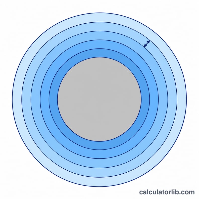
Turn a 50 mm bar down to 40 mm over 100 mm with 2 mm approach/overrun, 2.5 mm depth of cut, 1000 RPM and 0.2 mm/rev. The feed rate is 200 mm/min and the radial stock is 5 mm, so two passes are needed.
$$T_c = \frac{2 \times (100 + 2)}{1000 \times 0.2} = 1.02\,\text{min}$$Adding 30 s (0.5 min) of non-cutting time gives 1.52 min per part, or 15.2 min for 10 parts.
Typical Cutting Speeds and Feeds for Turning
The table gives general starting points for coated carbide inserts in stable, rigid setups with coolant where appropriate. Actual values depend on the insert grade, machine rigidity, workpiece hardness and the required tool life. The tool manufacturer's catalogue data always takes precedence over these figures.
| Workpiece material | Cutting speed Vc (m/min) | Roughing feed (mm/rev) | Finishing feed (mm/rev) | Roughing depth of cut (mm) | Finishing depth of cut (mm) |
|---|---|---|---|---|---|
| Free-cutting steel | 180–300 | 0.25–0.5 | 0.05–0.2 | 2–5 | 0.2–0.5 |
| Medium carbon steel | 150–220 | 0.2–0.5 | 0.05–0.2 | 2–4 | 0.2–0.5 |
| Stainless steel (austenitic) | 100–180 | 0.2–0.4 | 0.05–0.15 | 1.5–3 | 0.2–0.5 |
| Aluminium alloys | 300–600 | 0.2–0.5 | 0.05–0.2 | 2–5 | 0.2–0.5 |
| Grey cast iron | 120–220 | 0.25–0.5 | 0.1–0.2 | 2–5 | 0.2–0.5 |
| Brass (free-cutting) | 200–400 | 0.2–0.5 | 0.05–0.2 | 2–4 | 0.2–0.5 |
| Titanium alloys | 40–80 | 0.15–0.3 | 0.05–0.15 | 1–3 | 0.2–0.5 |
Converting cutting speed to RPM
The spindle speed follows from the cutting speed and the workpiece diameter at the cut:
$$n = \frac{1000 \cdot V_c}{\pi \cdot D}$$
where \(n\) is in rev/min, \(V_c\) in m/min and \(D\) in mm. For example, \(V_c = 200\) m/min on a 50 mm diameter gives \(n = \frac{1000 \times 200}{\pi \times 50} \approx 1273\) RPM. As the diameter shrinks during roughing, the RPM needed for a constant Vc increases; machines with constant surface speed (G96) do this automatically, and you should enter a representative RPM for fixed-RPM (G97) programs.
Scenario Comparison: How Parameters Change Cycle Time
All scenarios use the same part: start diameter 50 mm, final diameter 40 mm (radial stock 5 mm), cut length 100 mm, approach + overrun 2 mm (so \(L + A = 102\) mm), non-cutting time 30 s (0.5 min) and 10 parts. The formulas are:
$$N = \left\lceil \frac{5}{\text{DOC}} \right\rceil,\quad f_m = \text{RPM} \times f,\quad t_{\text{cut}} = \frac{N \cdot 102}{f_m},\quad t_{\text{part}} = t_{\text{cut}} + 0.5,\quad T_{\text{batch}} = 10 \cdot t_{\text{part}}$$
| Scenario | RPM | Feed (mm/rev) | DOC (mm) | Passes N | Feed rate (mm/min) | Cutting time (min) | Cycle time per part (min) | Batch time, 10 parts (min) |
|---|---|---|---|---|---|---|---|---|
| Baseline | 1000 | 0.2 | 2.5 | 2 | 200 | 2 × 10² / 200 = 1.02 | 1.52 | 15.2 |
| Higher feed | 1000 | 0.3 | 2.5 | 2 | 300 | 2 × 10² / 300 = 0.68 | 1.18 | 11.8 |
| Single pass (DOC 5 mm) | 1000 | 0.2 | 5 | 1 | 200 | 1 × 10² / 200 = 0.51 | 1.01 | 10.1 |
| Higher RPM | 1500 | 0.2 | 2.5 | 2 | 300 | 2 × 10² / 300 = 0.68 | 1.18 | 11.8 |
| Rough + finish split (two operations) | 1000 / 1500 | 0.3 / 0.1 | 4.5 / 0.5 | 1 + 1 = 2 | 300 / 150 | 0.34 + 0.68 = 1.02 | 1.52 | 15.2 |
Reading the results
- Feed and RPM act the same way on time: both scale the feed rate \(f_m\), so 0.2 → 0.3 mm/rev and 1000 → 1500 RPM each cut the time by one third. Higher RPM raises cutting speed and tool wear; higher feed raises cutting force and worsens surface finish.
- Depth of cut reduces the number of passes. Going from 2 passes to 1 halves the cutting time (1.02 → 0.51 min), provided the machine power, rigidity and insert can handle a 5 mm cut.
- Roughing plus finishing was calculated as two separate runs (rough 50 → 41 mm, finish 41 → 40 mm) and the times were added. In this case it takes the same cutting time as the baseline, but with a finishing pass at a fine feed that gives a better surface. It assumes the 30 s non-cutting time is unchanged; an extra tool change would add to it.
- The non-cutting time (0.5 min per part) is a fixed overhead, so it becomes a larger share of the cycle as cutting gets faster.
FAQ
Does this include tool wear or acceleration?
No. It is an ideal estimate at constant feed. Real cycle times are usually a little longer because of spindle ramp-up, dwell and tool changes, so use the non-cutting field to account for them.
What if I use constant surface speed?
With constant surface speed the RPM rises as the diameter shrinks. Enter an average RPM for a reasonable estimate.
Can I use it for finishing passes?
Yes. Set the depth of cut equal to the finishing allowance, or run the calculator separately for roughing and finishing and add the times.