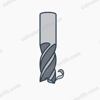
What is chip load?
Chip load (also called feed per tooth) is the thickness of material each cutting edge removes per revolution of the tool. It is the single most useful number in a feeds-and-speeds setup: it tells you whether each flute is taking a real bite or merely rubbing the workpiece. Too small a chip load generates heat and burnishes the surface instead of cutting it; too large a chip load deflects or snaps the cutter. This calculator works for router bits, end mills and face mills, in metric or imperial units, because the relationship is pure geometry and applies anywhere.
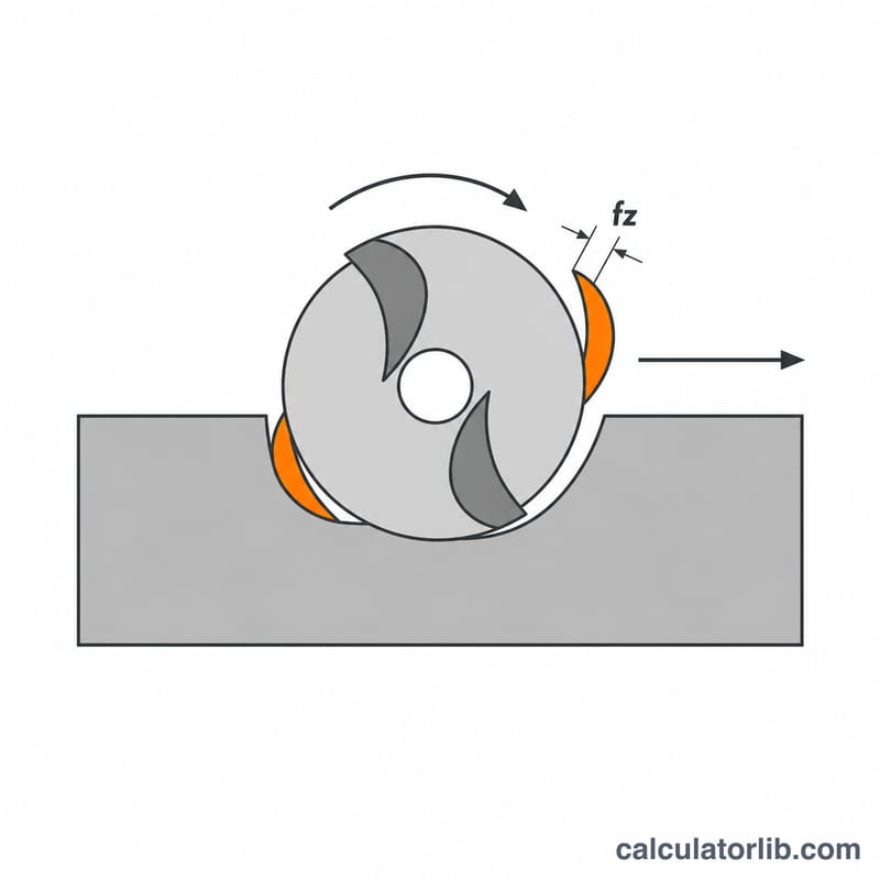
The formula explained
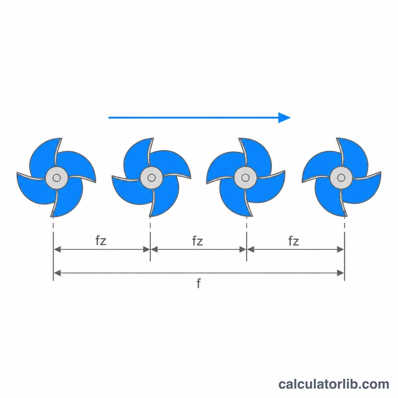
Each revolution presents \(Z\) cutting edges, and the spindle turns \(N\) times per minute, so the tool makes \(N \times Z\) edge engagements every minute. Dividing the distance travelled in that minute by the number of engagements gives the advance per edge:
$$CL = \frac{F}{N \times Z}$$where \(CL\) = chip load per tooth, \(F\) = feed rate in mm/min or in/min, \(N\) = spindle speed in RPM, and \(Z\) = number of flutes. Keep the units consistent: a feed in mm/min gives a chip load in mm; a feed in in/min gives a chip load in inches.
Worked example
A 2-flute 6 mm end mill runs at 12,000 RPM with a feed rate of 2,400 mm/min:
$$CL = \frac{2400}{12000 \times 2} = \frac{2400}{24000} = 0.10\,\text{mm}$$That is 100 microns per tooth, a healthy value for aluminium with a 6 mm cutter. If the chart calls for 0.05 mm instead, invert the formula: \(F = 0.05 \times 12000 \times 2 = 1200\) mm/min.
How to use the calculator
Pick your unit system, then enter the programmed feed rate, the spindle speed you actually run, and the flute count stamped on the cutter. Add a target chip load from the manufacturer chart and the calculator returns the feed rate that hits it, plus a ratio comparing your current setup to that target.
Typical Chip Load Ranges by Material and Tool Diameter
Chip load (feed per tooth) scales with cutter diameter far more than most beginners expect: a 1.5 mm micro end mill and a 12 mm end mill in the same material differ by roughly an order of magnitude in safe feed per tooth, because the thin shank simply cannot carry the cutting force. The table below gives starting feed-per-tooth bands for four diameter groups, with mm/tooth and in/tooth side by side.
| Material | Tool type assumed | 1–3 mm | 3–6 mm (≈1/8") | 6–12 mm (≈1/4") | 12–20 mm (≈1/2") |
|---|---|---|---|---|---|
| Softwood (pine, fir) | 2-flute upcut spiral router bit | 0.05–0.15 mm 0.002–0.006 in |
0.20–0.40 mm 0.008–0.016 in |
0.40–0.60 mm 0.016–0.024 in |
0.55–0.90 mm 0.022–0.035 in |
| Hardwood & plywood | 2-flute upcut spiral router bit | 0.04–0.12 mm 0.002–0.005 in |
0.15–0.30 mm 0.006–0.012 in |
0.25–0.45 mm 0.010–0.018 in |
0.40–0.65 mm 0.016–0.026 in |
| MDF / particleboard | 2-flute upcut spiral router bit | 0.05–0.13 mm 0.002–0.005 in |
0.18–0.33 mm 0.007–0.013 in |
0.28–0.50 mm 0.011–0.020 in |
0.45–0.70 mm 0.018–0.028 in |
| Acrylic & soft plastics | 1- or 2-flute O-flute / upcut router bit | 0.03–0.10 mm 0.001–0.004 in |
0.10–0.20 mm 0.004–0.008 in |
0.15–0.30 mm 0.006–0.012 in |
0.25–0.40 mm 0.010–0.016 in |
| Aluminium (6061-type) | 2–3 flute solid carbide end mill | 0.010–0.030 mm 0.0004–0.0012 in |
0.025–0.060 mm 0.001–0.0024 in |
0.050–0.110 mm 0.002–0.004 in |
0.100–0.200 mm 0.004–0.008 in |
| Brass & bronze | 2–4 flute solid carbide end mill | 0.010–0.025 mm 0.0004–0.001 in |
0.020–0.050 mm 0.0008–0.002 in |
0.040–0.090 mm 0.0016–0.0035 in |
0.080–0.160 mm 0.003–0.006 in |
| Mild / low-alloy steel | 4-flute solid carbide end mill | 0.005–0.015 mm 0.0002–0.0006 in |
0.013–0.030 mm 0.0005–0.0012 in |
0.025–0.060 mm 0.001–0.0024 in |
0.060–0.130 mm 0.0024–0.005 in |
| Stainless (300-series) | 4–5 flute solid carbide end mill | 0.005–0.013 mm 0.0002–0.0005 in |
0.010–0.025 mm 0.0004–0.001 in |
0.020–0.050 mm 0.0008–0.002 in |
0.050–0.100 mm 0.002–0.004 in |
How to use these bands
- Start low, in the bottom third of the band, especially on a light-frame hobby router or when the tool is held in a long collet extension or has a long flute length.
- Check the resulting feed rate against your machine. With \(\text{Feed} = \text{Chip Load} \times \text{RPM} \times \text{Flutes}\), a 6 mm 2-flute bit at 16,000 RPM and 4,000 mm/min gives a chip load of 0.125 mm per tooth — mid-band for hardwood, but far too aggressive for steel at the same diameter.
- These are slotting / moderate-engagement figures. At light radial engagement (trochoidal or adaptive toolpaths well under half the diameter) radial chip thinning means the programmed feed per tooth must be raised above the table value to keep the actual chip thickness in range — your CAM system normally applies that correction.
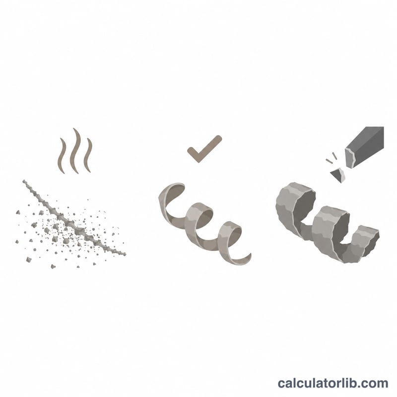
- Judge by the chips, not the number. Dust and a squealing cut mean the chip load is too low (rubbing, heat, premature edge wear); chatter, deflection or a broken tool means it is too high.
These values are starting points consistent with the shape of published tooling-manufacturer feeds-and-speeds data — for example Onsrud's router-tool charts for wood, plastics and non-ferrous metals, Harvey Tool / Helical micro and miniature end mill data, and Sandvik Coromant material-class recommendations for milling. They are deliberately conservative generic figures and are not a substitute for the data sheet of the tool in your spindle: the cutter maker's own recommendation, for that exact geometry, coating, flute count and depth of cut, always supersedes a general table like this one. Tooling catalogues also differ by region in the material groupings they use (ISO P/M/K/N/S/H classes in Europe, AISI/SAE designations in North America, JIS grades in Japan), so match the grade name on your stock to the grade in the chart you are reading.
Chip Load Unit Conversions
Chip load is quoted in millimetres per tooth in metric shops and in inches per tooth (IPT) in imperial ones, and tooling charts mix in microns and "thou" (thousandths of an inch). All of it comes from two exact factors:
$$1\ \text{in} = 25.4\ \text{mm} \qquad 1\ \text{mm} = \frac{1}{25.4}\ \text{in} \approx 0.03937\ \text{in}$$
- mm/tooth → in/tooth: divide by 25.4 (or multiply by 0.03937).
- in/tooth → mm/tooth: multiply by 25.4.
- mm/tooth → microns (µm): multiply by 1000. So 0.08 mm/tooth = 80 µm/tooth.
- in/tooth → thou: multiply by 1000, since 1 thou = 0.001 in. So 0.0035 in/tooth = 3.5 thou.
- Feed rate: mm/min ÷ 25.4 = in/min; in/min × 25.4 = mm/min.
Common chip-load equivalents
| mm/tooth | Microns/tooth | in/tooth (exact) | in/tooth (rounded) | Thou |
|---|---|---|---|---|
| 0.025 mm | 25 µm | 0.000984 in | 0.001 in | 1 thou |
| 0.05 mm | 50 µm | 0.001969 in | 0.002 in | 2 thou |
| 0.10 mm | 100 µm | 0.003937 in | 0.004 in | 4 thou |
| 0.25 mm | 250 µm | 0.009843 in | 0.010 in | 10 thou |
| 0.50 mm | 500 µm | 0.019685 in | 0.020 in | 20 thou |
| 0.0254 mm | 25.4 µm | 0.001 in | 0.001 in | 1 thou |
| 0.127 mm | 127 µm | 0.005 in | 0.005 in | 5 thou |
| 0.254 mm | 254 µm | 0.010 in | 0.010 in | 10 thou |
The last three rows are the exact inch-based values; the first five are the round metric values most catalogues print. Note that "0.025 mm = 0.001 in" is a convenient approximation, not an identity — the exact equivalent of 1 thou is 0.0254 mm, a 1.6% difference that is irrelevant for feed setting but matters if you are converting a tolerance.
Feed per tooth, feed per revolution and feed rate
Three quantities describe the same motion at different scales. With \(f_z\) the feed per tooth (chip load), \(f_n\) the feed per revolution, \(n\) the spindle speed in RPM and \(z\) the flute count:
$$f_n = f_z \times z \qquad\text{and}\qquad v_f = f_z \times z \times n = f_n \times n$$
In imperial terms the same chain reads IPR = IPT × flutes and IPM = IPT × flutes × RPM. Rearranged, chip load is simply the feed rate divided by the number of tooth passes per minute:
$$f_z = \frac{v_f}{n \times z}$$
Worked conversion
A 12.7 mm (1/2") 2-flute upcut router bit runs at 18,000 RPM with a programmed feed of 14,400 mm/min. Working through the chain:
- Feed per revolution: \(f_n = 14{,}400 \div 18{,}000 = 0.80\ \text{mm/rev}\)
- Feed per tooth: \(f_z = 0.80 \div 2 = \) 0.40 mm per tooth
- In inches: \(0.40 \div 25.4 = 0.01575\ \text{in/tooth} \approx 15.7\ \text{thou}\), i.e. 400 µm/tooth
- Feed rate in imperial: \(14{,}400 \div 25.4 = 566.9\ \text{in/min}\)
- Check: \(0.01575 \times 2 \times 18{,}000 = 567\ \text{in/min}\) ✓
Switching the calculator's units selector performs these conversions for you, but it is worth doing one by hand: a chip load quoted as "0.016" is 0.016 in/tooth in an American catalogue and 0.016 mm/tooth in a European one — a 25-fold difference, and the single most common cause of a snapped end mill when copying numbers between charts.
FAQ
What chip load should I aim for? It depends on tool diameter and material. As a rough guide, small router bits under 3 mm often run 0.01-0.05 mm per tooth, while 6-12 mm cutters in wood or aluminium run 0.05-0.25 mm. Always start from the tool maker data sheet.
Does depth of cut change chip load? No. Depth and width of cut change chip thinning, cutting forces and material removal rate, but chip load per tooth comes only from feed, RPM and flute count.
Why do my chips look like dust? Dust means the chip load is far too low, usually from high RPM with a timid feed. Raise the feed rate or drop the spindle speed until chips form visible flakes that carry heat away.