What This Calculator Does
When molten plastic cools inside a mold it contracts, so the finished part is always smaller than the cavity that formed it. This tool sizes the mold cavity so that, after the material shrinks, the part lands on your target dimension. It is essential for toolmakers, mold designers, and injection molding engineers who must cut steel to the correct size the first time.
The Formula
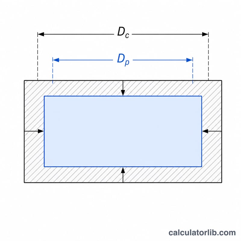
Shrinkage rate \(S\) is expressed as a percent of the cavity dimension. To recover the finished part dimension \(D_{\text{part}}\) after shrinkage, the cavity \(D_{\text{cavity}}\) must be:
$$D_{\text{cavity}} = \frac{D_{\text{part}}}{1 - \frac{S}{100}}$$Here \(D_{\text{part}}\) = desired final part size in mm, and \(S\) = material shrinkage rate in percent (for example ABS is roughly \(0.5\%\) and polypropylene \(1.5\%\) to \(2.5\%\)). The extra steel machined into the cavity is \(\Delta = D_{\text{cavity}} - D_{\text{part}}\).
How to Use It
Enter the dimension you want the molded part to have once it is cool, then enter the shrinkage rate from your resin datasheet. The calculator returns the cavity dimension to machine and the compensation that was added.
Worked Example
Suppose the target part dimension is \(100\,\text{mm}\) and the material shrinks \(2\%\):
$$D_{\text{cavity}} = \frac{100}{1 - 0.02} = \frac{100}{0.98} = 102.041\,\text{mm}$$So the cavity is cut to \(102.041\,\text{mm}\), adding \(2.041\,\text{mm}\) of compensation. After the part cools it shrinks back to the intended \(100\,\text{mm}\).
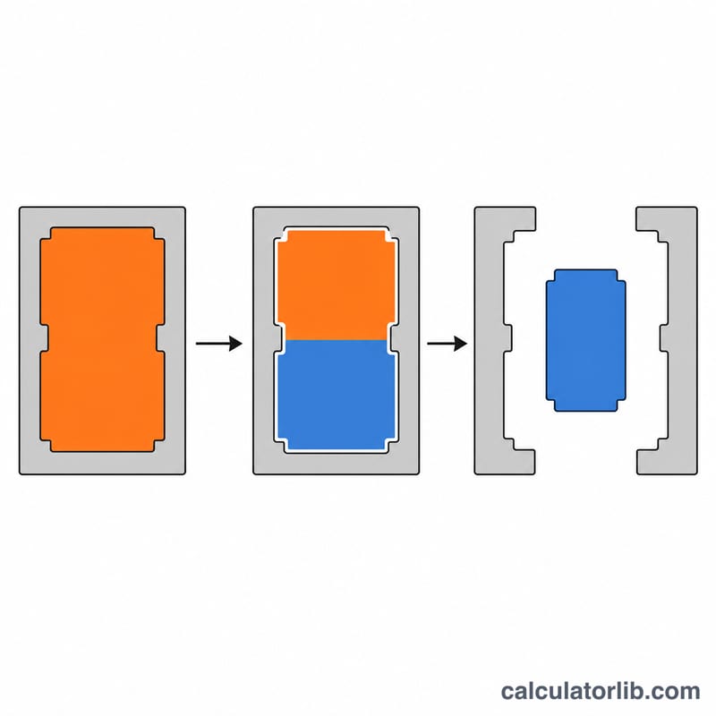
Typical Shrinkage Rates by Plastic Material
The table lists typical mold shrinkage ranges for common unfilled resins. Use them for early estimates only. The real value depends on the grade, wall thickness, gate location, packing pressure, melt and mold temperature, and cooling time. If you have the resin supplier's datasheet for your grade, use its figure instead of these.
| Group | Material | Typical shrinkage range (%) |
|---|---|---|
| Amorphous (low shrinkage) | ABS | ~0.4–0.7 |
| PC (polycarbonate) | ~0.5–0.7 | |
| PMMA (acrylic) | ~0.2–0.8 | |
| PS (general-purpose polystyrene) | ~0.3–0.6 | |
| HIPS (high-impact polystyrene) | ~0.4–0.7 | |
| PVC, rigid | 0.1–0.5 | |
| Semi-crystalline (high shrinkage) | PP (polypropylene) | 1.0–2.5 |
| HDPE | 1.5–3.0 | |
| LDPE | 1.5–5.0 | |
| POM (acetal) | 1.8–2.5 | |
| PA6 (nylon 6) | 0.7–1.5 | |
| PA66 (nylon 6/6) | 0.8–1.5 | |
| PBT | 1.5–2.0 | |
| PET | ~0.2–2.0 (low when molded amorphous, high when crystallized) | |
| Glass-filled PA / PBT | ~0.2–0.8 |
Why the two groups differ: semi-crystalline polymers form tightly packed crystalline regions as they cool. That packing makes them shrink much more than amorphous polymers, and it also makes their shrinkage more sensitive to cooling rate and mold temperature.
Glass-fiber fillers lower shrinkage a lot, but they also make it anisotropic. The fibers line up with the melt flow, so shrinkage along the flow direction is usually lower than shrinkage across it. For filled grades, check the datasheet for separate flow-direction and transverse values, and use the right one for each part dimension.
Cavity Size Across Different Materials
This table holds the target part dimension fixed at 100 mm and changes only the shrinkage rate. Each cavity dimension is calculated with
$$D_{cavity} = \frac{100}{1 - S/100}$$The compensation is the extra length machined into the cavity, \(D_{cavity} - 100\). Example materials are taken from the typical ranges above.
| Example material | Shrinkage S (%) | Cavity dimension (mm) | Compensation (mm) |
|---|---|---|---|
| ABS | 0.5 | 100.503 | 0.503 |
| PA6 | 1.0 | 101.010 | 1.010 |
| PP / PBT | 1.5 | 101.523 | 1.523 |
| POM (acetal) | 2.0 | 102.041 | 2.041 |
| HDPE / PP (high end) | 2.5 | 102.564 | 2.564 |
At 2.5% shrinkage, for example, the substitution is \(100 / (1 - 0.025) = 100 / 0.975 = 102.564\) mm.
Why the approximation falls short: a common shortcut is \(D_{cavity} \approx 100 \times (1 + S/100)\). At 2.5% this gives
$$100 \times 1.025 = 102.500\ \text{mm}$$The exact formula gives 102.564 mm. That is a difference of \(102.564 - 102.500 = 0.064\) mm, so a cavity cut with the shortcut produces a part about 0.064 mm undersized. The shortcut's error grows roughly with the square of the shrinkage rate. It is negligible for low-shrink amorphous resins, but on precision features in high-shrink semi-crystalline materials it can use up a tight tolerance.
FAQ
Why divide instead of just adding the percentage? Shrinkage is measured relative to the cavity size, not the part size. Dividing by \(1 - S/100\) is the exact inverse and is more accurate than multiplying the part by \(1 + S/100\).
Where do I get the shrinkage rate? The resin manufacturer publishes it on the material datasheet, often as a range. Use the value for your wall thickness and gate conditions.
Does it apply to every dimension? Apply the calculation independently to each critical linear dimension; shrinkage can differ along and across the flow direction.